Integrated normal-pressure shale gas drainage gas recovery and on-site treatment device

A drainage gas recovery and on-site treatment technology, which is applied in the fields of fluid extraction, earth drilling, gas/liquid distribution and storage, etc. It can solve problems such as poor purity of shale gas collection, blockage of filter mechanism, time-consuming and laborious disassembly and removal, etc.

Active Publication Date: 2022-04-08
SICHUAN KEYUAN TESTING CENT OF ENG TECH CO LTD
View PDF10 Cites 0 Cited by
  • Summary
  • Abstract
  • Description
  • Claims
  • Application Information

AI Technical Summary

Problems solved by technology

[0003] When the existing shale gas is exploited, the shale gas first needs to go through the separation step to separate and filter the shale gas itself. The separation operation is realized by the medium’s interception of solid particles and liquid droplets in the gas. It can separate fine solid dust and liquid mist droplets in the gas, and the separation accuracy is high. Natural gas, but the traditional gas-water separation filter device’s own filter mechanism is set at Inside the device, the filter device itself is generally integrated, and it is time-consuming and laborious to disassemble and remove. As a result, when the filter mechanism is used for long-term filtration in the gas-water separation device, the surface of the filter mechanism itself will absorb and accumulate many particles and impurities, which is easy It will block the filter mechanism itself, affect the filterability of shale gas self-collection, and make the purity of shale gas self-collection poor

Method used


Image

  • Integrated normal-pressure shale gas drainage gas recovery and on-site treatment device
  • Integrated normal-pressure shale gas drainage gas recovery and on-site treatment device
  • Integrated normal-pressure shale gas drainage gas recovery and on-site treatment device

Examples


Embodiment

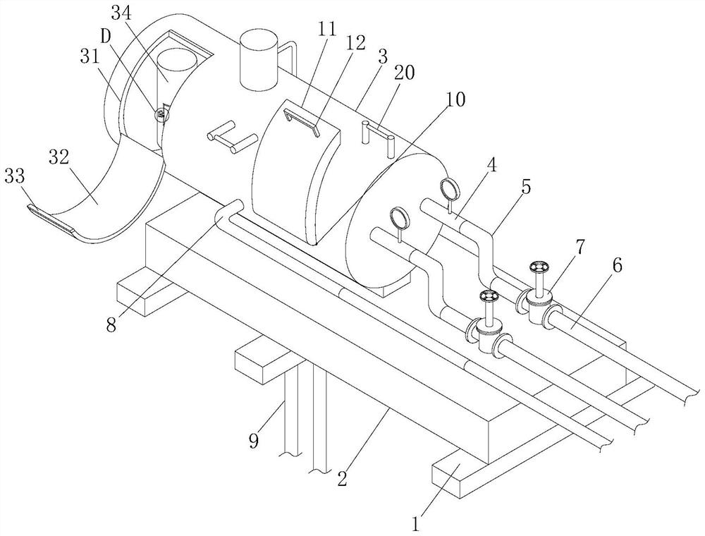
[0039] Embodiment: integrated atmospheric pressure shale gas drainage gas recovery and on-site treatment device, such as Figure 1-Figure 11As shown, it includes several equidistantly arranged bottom support mechanisms 1 and a load-bearing mechanism 2 fixedly installed on the top of the bottom support mechanism 1. The load-carrying mechanism 2 is a rectangular structure. The collection tank 3 is a circular internal hollow structure, and one of the outer surfaces of the collection tank 3 is fixedly installed with a delivery pipe 4 communicating with the inside of the collection tank 3 for transporting gas, and the delivery pipe 4 is far away from the end of the collection tank 3 A connection pipe 6 that can communicate with the inside of the delivery pipe 4 is fixedly connected to the connection sleeve 5. The connection pipe 5 has a Z-shaped internal hollow structure, and the inside of the connection pipe 6 is provided with a control that can control the delivery volume inside t...


PUM


Abstract

The invention relates to the technical field of petroleum and natural gas extraction devices, and discloses an integrated normal-pressure shale gas drainage gas recovery and on-site treatment device which comprises a plurality of bottom supporting mechanisms arranged at equal intervals and a bearing mechanism fixedly installed on the tops of the bottom supporting mechanisms. A gas-water separation device in the collection tank can perform primary gas-water separation on natural gas collected in a rock stratum, a first filtering mechanism and a second filtering mechanism in the gas-water separation device can be matched with an external filtering mechanism to filter and convey the gas, and firstly, a sealing bin door can be opened from the collection tank; according to the gas-water separation device, the filter mechanism in the gas-water separation device directly moves to the outside of the gas-water separation device along with the control door at the same time, the filter mechanism is replaced after being detached, and then the control door is closed, sealed and fixed with the inside of the gas-water separation device again, so that the cleanliness of the filter mechanism is ensured, and the service life of the gas-water separation device is prolonged. The filterability of fuel gas is improved, and the purity of shale gas is improved.

Description

technical field [0001] The invention relates to the technical field of oil and natural gas exploitation devices, in particular to an integrated normal-pressure shale gas drainage gas recovery and on-site treatment device. Background technique [0002] Shale gas refers to organic matter-rich, mature dark mud shale or high-carbon mud shale, which has a certain commercial value due to the adsorption of organic matter or the existence of fractures and matrix pores in the rock, so that it is stored and preserved. , natural gas of pyrolysis origin and mixed origin of the two, shale gas is unconventional natural gas that occurs in organic-rich shale-based reservoir rock series. [0003] When the existing shale gas is exploited, the shale gas first needs to go through the separation step to separate and filter the shale gas itself. The separation operation is realized by the medium’s interception of solid particles and liquid droplets in the gas. It can separate fine solid dust and...

Claims


Application Information

Patent Timeline
Patent Type & Authority Applications(China)
IPC IPC(8): E21B43/34E21B17/00E06C9/00F17D1/02F17D3/14
Inventor 尹中山戚明辉王东强刘虎徐强
Owner SICHUAN KEYUAN TESTING CENT OF ENG TECH CO LTD
Why Eureka
Try Eureka