Power-consumption-free carbon dioxide multi-path recovery device in coal mine air shaft

A carbon dioxide recovery device technology, applied in mine/tunnel ventilation, mining equipment, chemical instruments and methods, etc., can solve problems such as poor condensation effect of carbon dioxide, waste of carbon dioxide utilization value, environmental pollution, etc.

Pending Publication Date: 2022-04-08
TIANDI SCI & TECH CO LTD +1
View PDF0 Cites 0 Cited by
  • Summary
  • Abstract
  • Description
  • Claims
  • Application Information

AI Technical Summary

Problems solved by technology

[0002] In the coal mining industry, there is a large amount of carbon dioxide in the airflow of the coal mine air shaft, and the direct discharge into the air not only causes serious pollution to the environment, aggravates the greenhouse effect, but also greatly wastes the use value of carbon dioxide. A large waste of energy, so it is necessary to recover the carbon dioxide in the airflow discharged from the coal mine air shaft. Since the temperature of the airflow discharged from the coal mine air shaft reaches 30-40 ° C, directly condensing the airflow to recover the carbon dioxide will cause the carbon dioxide condensation effect to be relatively poor Difference

Method used


Image

  • Power-consumption-free carbon dioxide multi-path recovery device in coal mine air shaft
  • Power-consumption-free carbon dioxide multi-path recovery device in coal mine air shaft
  • Power-consumption-free carbon dioxide multi-path recovery device in coal mine air shaft

Examples


Embodiment Construction

[0040]Embodiments of the present application are described in detail below, examples of which are shown in the drawings, wherein the same or similar reference numerals denote the same or similar elements or elements having the same or similar functions throughout. The embodiments described below by referring to the figures are exemplary, and are only for explaining the present application, and should not be construed as limiting the present application. On the contrary, the embodiments of the present application include all changes, modifications and equivalents falling within the spirit and scope of the appended claims.

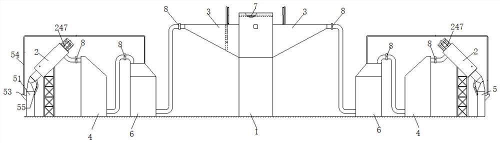
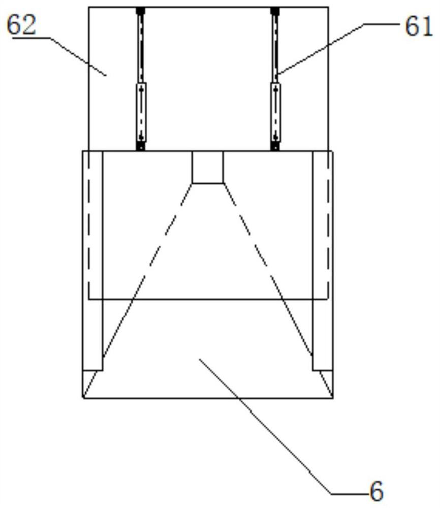
[0041] figure 1 It is a structural schematic diagram of a non-power consumption carbon dioxide multi-channel recovery device proposed in an embodiment of the application.

[0042] see Figure 1-10 A multi-channel recovery device for carbon dioxide without power consumption in a coal mine air shaft, comprising an air shaft 1, a carbon dioxide condensing mec...


PUM


Abstract

The invention provides a power-consumption-free carbon dioxide multi-path recovery device in a coal mine air shaft, which comprises an air shaft, a dust remover, a gas collection chamber and a carbon dioxide condensation mechanism, and a plurality of adjustable variable-speed air ducts communicated with the air shaft are arranged on the peripheral side of the side wall of the air shaft; the drift diameter of the adjustable variable-speed air duct is gradually reduced in the direction from an air inlet to an air outlet of the adjustable variable-speed air duct; the dust remover is connected with an air outlet of the adjustable variable-speed air duct, the air collection chamber is connected with the dust remover, and the carbon dioxide condensation mechanism is connected with the air collection chamber and used for condensing the received dried airflow so that carbon dioxide in the airflow can be condensed into liquid carbon dioxide. According to the device, primary cooling of the airflow temperature is achieved through the adjustable variable-speed air duct, cooling is conducted through the dust remover and the air collecting chamber in sequence, dry airflow obtained after three times of cooling is introduced into the carbon dioxide condensation mechanism to be condensed, and the condensation effect of carbon dioxide is improved.

Description

technical field [0001] The application relates to the technical field of coal mines, in particular to a multi-channel recovery device for carbon dioxide without power consumption in coal mine air shafts. Background technique [0002] In the coal mining industry, there is a large amount of carbon dioxide in the airflow of the coal mine air shaft, and the direct discharge into the air not only causes serious pollution to the environment, aggravates the greenhouse effect, but also greatly wastes the use value of carbon dioxide. A large waste of energy, so it is necessary to recover the carbon dioxide in the airflow discharged from the coal mine air shaft. Since the temperature of the airflow discharged from the coal mine air shaft reaches 30-40 ° C, directly condensing the airflow to recover the carbon dioxide will cause the carbon dioxide condensation effect to be relatively poor. Difference. Contents of the invention [0003] This application aims to solve one of the techn...

Claims


Application Information

Patent Timeline
IPC IPC(8): E21F1/00E21D9/14F03G7/04B01D47/06B01D53/26B01D53/00
CPCY02P70/10B01D47/06B01D53/00B01D53/26E21D9/14E21F1/00F03G7/04
Inventor 徐亚军庞晓亮张德生李明忠
Owner TIANDI SCI & TECH CO LTD
Why Eureka
Try Eureka