

Motor device
A motor and motor shaft technology, which is applied in the direction of electromechanical devices, manufacturing tools, mechanical equipment, etc., can solve the problem of increasing the axial size of the brake, and achieve the effect of miniaturizing the axial size
- Summary
- Abstract
- Description
- Claims
- Application Information
AI Technical Summary
Problems solved by technology
Method used
Image

Examples
no. 1 Embodiment approach
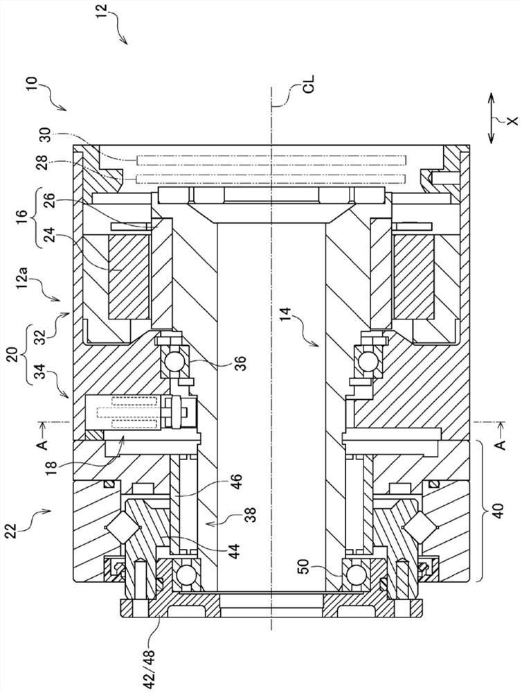
[0025] refer to figure 1 . The motor device 10 of the present embodiment is incorporated into the joint portion 12 a of the industrial robot 12 . The industrial robot 12 of the present embodiment is a collaborative robot that works in cooperation with humans.
[0026] The motor device 10 of the present embodiment mainly includes a motor shaft 14 , a motor 16 , a brake 18 , a case 20 , and a reduction gear 22 .
[0027] The motor shaft 14 is used to transmit the rotational power generated by the motor 16 to a driven component (not shown). The driven member of the present embodiment is the second arm of the industrial manipulator 12 connected to the first arm via the joint portion 12 a. Hereinafter, the direction along the rotation centerline CL of the motor shaft 14 is referred to as the axial direction X, and the circumferential direction and radial direction of a circle centered on the rotation centerline CL are referred to as "circumferential" and "radial", respectively. ...
no. 2 Embodiment approach
[0088] refer to Figure 8 and Figure 9 . In the pressing mechanism 60 of the first embodiment, the pressing member 76 is coupled to the brake shoe 58 in order to move the brake shoe 58 from the brake position Pa to the brake release position Pb. In contrast, the pressing member 76 of this embodiment is not connected to the brake shoe 58 . Further, the pressing mechanism 60 of the present embodiment includes an urging member for urging the brake shoe 58 in the retraction direction Db2 in order to move the brake shoe 58 from the brake position Pa to the brake release position Pb. 100A, 100B.
[0089] The urging members 100A and 100B of the present embodiment are tension springs, and urge the brake shoe 58 based on an elastic restoring force of elastic deformation. Tension springs (ie, urging members 100A, 100B) connect brake housing 34 and brake shoe 58 . The urging members 100A and 100B include: a first urging member 100A corresponding to the first wedge-shaped space 56A;...
no. 3 Embodiment approach
[0097] refer to Figure 11 . The motor device 10 of this embodiment differs from the first embodiment in that the structure of the pressing mechanism 60 is different. In the pressing mechanism 60 of the present embodiment, the non-electric drive unit 78 and the electric drive unit 80 are disposed at different positions from each other. Next, this will be described in detail. The electric drive unit 80 is accommodated in a mechanism accommodating portion 110 provided at a location different from the accommodating recessed portion 54 of the brake housing 34 . The direction perpendicular to the advancing and retreating direction Db and the axial direction X of the pressing member 76 is referred to as an orthogonal direction De. At this time, the electric drive unit 80 is arranged at a position shifted from the brake shoe 58 in the orthogonal direction De. The non-electric drive unit 78 is housed in the housing recess 54 similarly to the first embodiment.
[0098] In the firs...
PUM
 Abstract
Description
Claims
Application Information