Roof condensation type photovoltaic power generation device

A photovoltaic power generation and concentrating technology, which is applied to photovoltaic power generation, photovoltaic modules, support structures of photovoltaic modules, etc., can solve the problems of reduced light conduction efficiency of convex lenses, unfavorable high-efficiency photovoltaic power generation, and large photovoltaic power generation devices, and achieves a small structure. , to ensure the efficiency of light transmission, the effect of small footprint

Active Publication Date: 2022-04-08
LIAONING TECHNICAL UNIVERSITY
View PDF6 Cites 0 Cited by
  • Summary
  • Abstract
  • Description
  • Claims
  • Application Information

AI Technical Summary

Problems solved by technology

[0003] However, photovoltaic power generation devices are generally large, and the equipment required for the rotation and adjustment process is large, occupying a large area, and high energy consumption. At the same time, dust will stick to the convex lens of the photovoltaic power generation device after a long time of use. Reduced, not conducive to high-efficiency photovoltaic power generation

Method used


Image

  • Roof condensation type photovoltaic power generation device
  • Roof condensation type photovoltaic power generation device
  • Roof condensation type photovoltaic power generation device

Examples


Embodiment 1

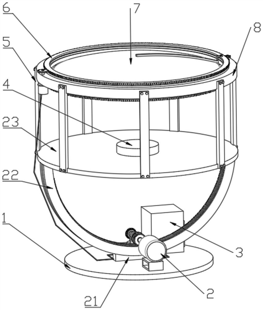
[0051] Such as figure 1 , 2 , 3, 4, 5, 6 and 7 show a roof concentrating photovoltaic power generation device, including a base 1, a control box 3, a solar panel 4 and a convex lens 7, the control box 3 is fixedly installed on the top of the base 1, and the base 1 The top is provided with an angle adjustment component 2;

[0052] The angle adjustment assembly 2 is connected with a protection structure 9 for protection;

[0053] The top of the angle adjustment assembly 2 is provided with a solar panel 4 for power generation;

[0054] The top of the angle adjustment assembly 2 is fixed with supporting plates 5 at equal intervals along the circumferential direction, the top of the supporting plates 5 is connected with a mounting ring 8, the lower end of the inner wall of the mounting ring 8 is provided with a supporting ring 11, and the top of the supporting ring 11 has an outer ring 10 and a convex lens through screws. 7 is installed in the outer ring 10;

[0055]The mountin...

Embodiment 2

[0058] Embodiment 2 is a further improvement to Embodiment 1.

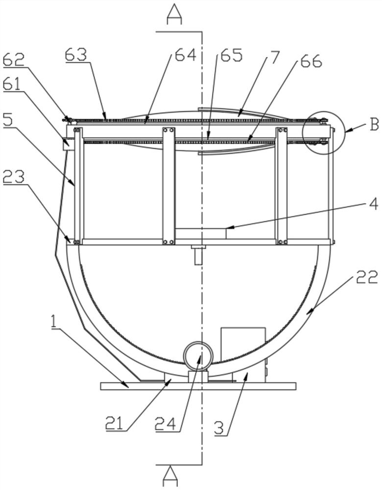
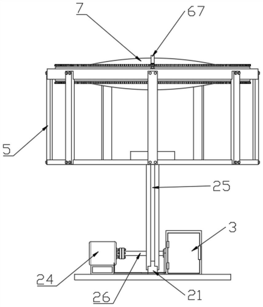
[0059] Such as figure 1 , 2 , 3, 4 and 6 further, the angle adjustment assembly 2 includes an arc-shaped guide rail 21, a semi-circular ring gear 22, a top plate 23, a first drive motor 24, an arc-shaped limit chute 25, a transverse shaft 26 and a first A ring gear 27, the first driving motor 24 is installed on the top of the base 1, the output shaft of the first driving motor 24 is connected to the horizontal shaft 26 through a coupling, the horizontal shaft 26 is equipped with the first ring gear 27, and the arc guide rail 21 is installed on On the top of the base 1, the outer wall of the semi-circular gear 22 is provided with an arc-shaped limit chute 25 used in conjunction with the arc guide rail 21, and the inner wall of the semi-circular gear 22 is meshed with the first gear 27 through a gear block, and the top of the semi-circular gear 22 is provided with There is a top plate 23, a support seat 28 is inst...

Embodiment 3

[0062] Embodiment 3 is a further improvement to Embodiment 2.

[0063] Such as Figure 4 , 5 , the protective structure 9 shown in 6 and 8 comprises installation tube 91, the 7th ring gear 92, spring 93, electromagnet 94, iron sliding plate 95, tooth plate 96 and sliding block 97, and installation tube 91 and electromagnet 94 install On the top of the base 1, the electromagnet 94 is arranged in the installation cylinder 91, the installation cylinder 91 is provided with a spring 93, the top of the spring 93 is provided with an iron sliding plate 95, and the top of the iron sliding plate 95 is fixed with a sliding block 97, and the installation cylinder 91 The top is fitted and slidably connected with the sliding block 97 through a straight hole, the top of the sliding block 97 is fixed with a toothed plate 96, and the top of the toothed plate 96 is meshed with the seventh ring gear 92, and the seventh ring gear 92 is installed at the outer end of the transverse shaft 26. The ...


PUM


Abstract

The invention discloses a roof condensation type photovoltaic power generation device, which belongs to the technical field of photovoltaic power generation and comprises a base, a control box, a solar panel and a convex lens, the control box is fixedly mounted at the top of the base, and an angle adjusting assembly is arranged at the top of the base; the angle adjusting assembly is connected with a protection structure used for protection. A solar panel for power generation is arranged at the top of the angle adjusting assembly; supporting plates are fixed to the top of the angle adjusting assembly at equal intervals in the circumferential direction, mounting rings are connected to the tops of the supporting plates, and convex lenses are arranged in the mounting rings. The mounting ring is connected with a cleaning assembly for cleaning dust of the convex lens; in this way, the device is small in occupied area, low in energy consumption and convenient to rotate, adjust and use.

Description

technical field [0001] The invention relates to the technical field of photovoltaic power generation, in particular to a rooftop concentrating photovoltaic power generation device. Background technique [0002] A photovoltaic power generation system is a power generation system that uses solar cells to directly convert solar energy into electrical energy. The photovoltaic power generation system is installed in many places with good lighting. The photovoltaic power generation device installed on the roof of the house is not easily blocked by tall buildings, and the power generation efficiency is relatively high. [0003] However, photovoltaic power generation devices are generally large, and the equipment required for the rotation and adjustment process is large, occupying a large area, and high energy consumption. At the same time, dust will stick to the convex lens of the photovoltaic power generation device after a long time of use. It is not conducive to high-efficiency...

Claims


Application Information

Patent Timeline
Patent Type & Authority Applications(China)
IPC IPC(8): H02S20/24H02S20/30H02S40/10
CPCY02E10/50Y02B10/10
Inventor 任志玲崔国庆
Owner LIAONING TECHNICAL UNIVERSITY
Why Eureka
Try Eureka