
Electrostatic powder spraying process for aluminum profile

A technology for electrostatic powder and aluminum profiles, which is used in liquid spraying equipment, coatings, devices for applying liquid to surfaces, etc., and can solve problems such as uneven spray paint surface and uneven distribution of positive charges.

Pending Publication Date: 2022-04-12
容创友
View PDF5 Cites 0 Cited by
  • Summary
  • Abstract
  • Description
  • Claims
  • Application Information

AI Technical Summary

Problems solved by technology

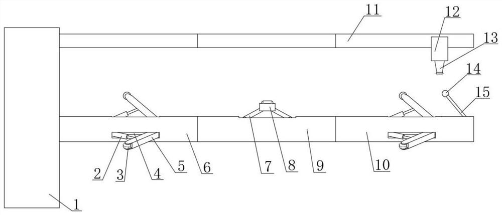
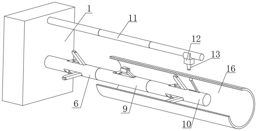
[0004] Based on the technical problem of uneven spraying paint surface caused by uneven positive charge distribution of existing aluminum tube spraying equipment, this invention proposes an electrostatic powder spraying process for aluminum profiles

Method used


Image

  • Electrostatic powder spraying process for aluminum profile
  • Electrostatic powder spraying process for aluminum profile
  • Electrostatic powder spraying process for aluminum profile

Examples


Embodiment 1

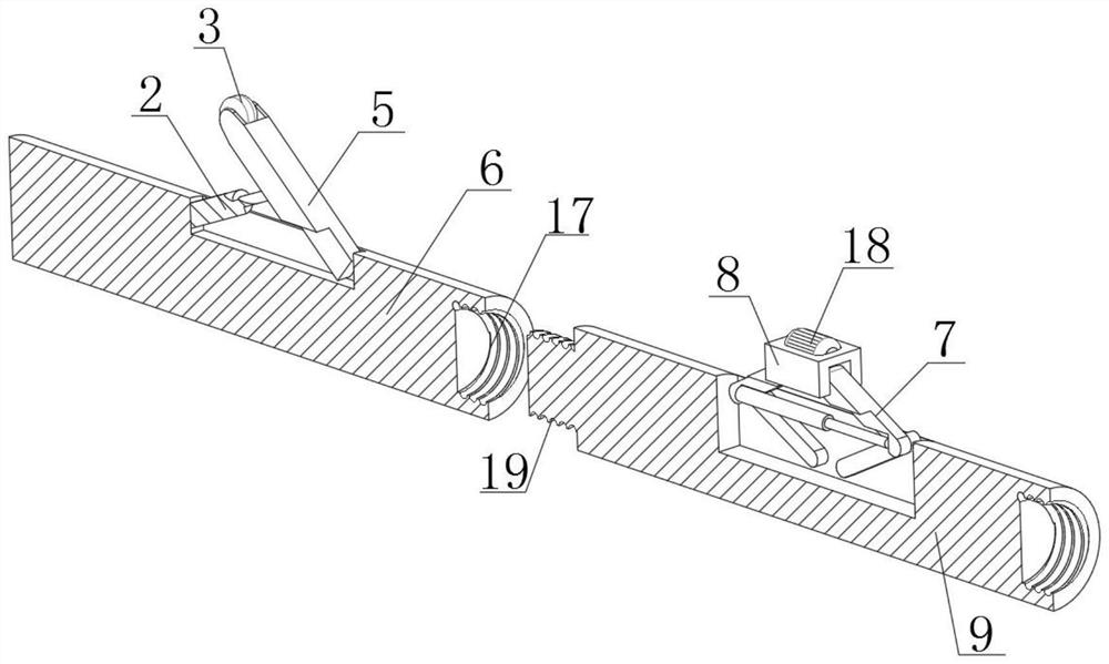
[0031] Refer Figure 1 - Figure 5An aluminum profile electrostatic powder spray process, including suitable positions that secure the fixed base in the workshop before preparing, and assemble the fixed base rod, the power base rod, and the fixed end rod according to the length of the spray aluminum tube, and install it. Suitable order is installed, and the extension rod is held in the top, and the operator puts one end of the aluminum tube at one end of the fixed end rod, and gradually advances, by controlling the first electric push rod and the second electric push rod. However, the top of the support wheel and the drive wheel can be inserted with the peripheral inner wall of the aluminum tube, and the conductive contact ball can be in contact with the inner wall of the aluminum pipe, so that the body of the aluminum tube has a positive charge, during the spraying process, by control For electrical conductivity of the electromagnetic circle, the top magnetic base can be applied to...

Embodiment 2

[0041] Refer Figure 3 - Figure 7 , An aluminum profile electrostatic powder spray process, which is also included in the first embodiment.

[0042] In the present invention, a drying fixed top box 31, which is disposed horizontally disposed, and the bottom of the drying fixed top box 31 is fixed by a bolt, and a dry cylinder 32 disposed at the bottom of the drying fixed top box 31 is fixed by bolt. The bottom of the mouth 13 is fixedly provided with a vertically disposed annular painting holder 33, and the annular painting holder 33 is retained with the horizontal center line of the drying cylinder 32, and the bottom of the top rod 11 is extended to open the slide, and The inner wall sliding card of the chute has a vertically disposed sliding top block 30, and the bottom inner wall of the drying fixed top box 31 is fixedly provided with a horizontally disposed heat-conducting fin 37, and the inner wall of the drying fixed top box 31 is fixed. The horizontally disposed hot compress...


PUM


Abstract

The invention belongs to the technical field of aluminum profile machining, particularly relates to an aluminum profile electrostatic powder spraying process, and provides the following scheme aiming at the problem of non-uniform sprayed paint surface caused by non-uniform positive charge distribution of existing aluminum tube spraying equipment: fixing a fixed base at a proper position of a workshop before preparation; and the fixed base rod, the power base rod and the fixed end rod are assembled according to the length of the sprayed aluminum pipe, the fixed base rod, the power base rod and the fixed end rod are mounted in a proper sequence and stably fixed, and the extended ejector rod at the top is synchronously mounted. According to the device, in the moving process, the spraying position of the aluminum pipe is always kept at the vertical alignment position with a conductive contact arc plate where positive charges are generated all the time, so that the attraction force of the spraying position is always the same, and the uniform spraying effect can be stably kept; and the uniform spraying process can be carried out on the circumference of the aluminum pipe.

Description

Technical field [0001] The present invention relates to the field of aluminum profile processing techniques, and more particularly to an aluminum profile electrostatic powder spray process. Background technique [0002] Aluminum profiles are aluminum rods by hot melt, extrusion, to obtain different cross-sectional aluminum materials, and the production flow of aluminum profiles mainly include three processes of molten casting, squeezing, and coloring, wherein coloring mainly includes: oxidation, electrophoresis. Painting, fluorine spray, powder spray, wood grain transfer, etc. In the process of powder spraying, it is mainly sprayed with a negative-charged aluminum profile itself to achieve electrostatic spraying. Effect. [0003] Existing aluminum tube profiles have the following problems in the electrostatic spraying process: Since the standard aluminum tube length is four meters, during the spraying process, one end of the aluminum tube is electrically charged, which is positiv...

Claims


Application Information

Patent Timeline
Patent Type & Authority Applications(China)
IPC IPC(8): B05D7/14B05B5/08B05B5/14B05B5/10B05B5/16
CPCY02P70/10
Inventor 容创友
Owner 容创友
Learn More