
USB terminal cutting device

A terminal and cutting technology, which is applied in the field of USB terminal cutting devices, can solve the problems of not being able to meet the processing efficiency requirements, occupy a large space, and complicate the structure of the device, so as to improve the overall processing and assembly efficiency, meet the requirements of high processing efficiency, and simplify the device structure effect

Pending Publication Date: 2022-04-12
FREEPORT GUANGDONG PRECISION IND CO LTD
View PDF7 Cites 2 Cited by
  • Summary
  • Abstract
  • Description
  • Claims
  • Application Information

AI Technical Summary

Problems solved by technology

The structure of the device is complex and takes up a lot of space. In addition, the terminal strips need to be positioned separately during the cutting link and the plug-in link, especially in the plug-in link. Accuracy, resulting in the limitation of the overall processing and assembly efficiency, it is difficult to further improve, unable to meet the demand for higher processing efficiency

Method used


Image

  • USB terminal cutting device
  • USB terminal cutting device
  • USB terminal cutting device

Examples


Embodiment Construction

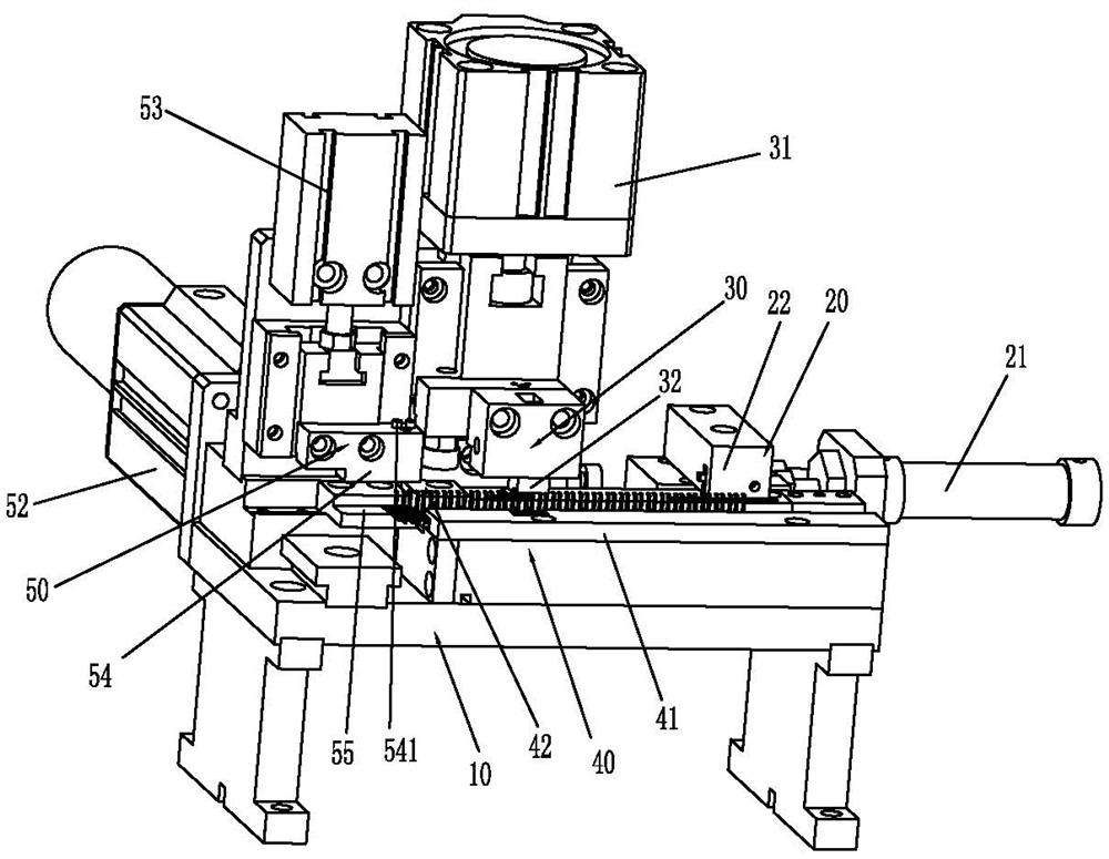
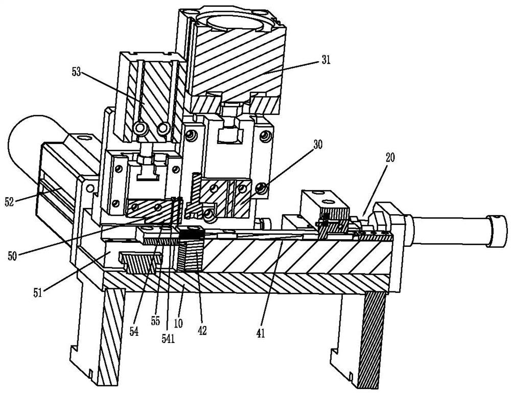
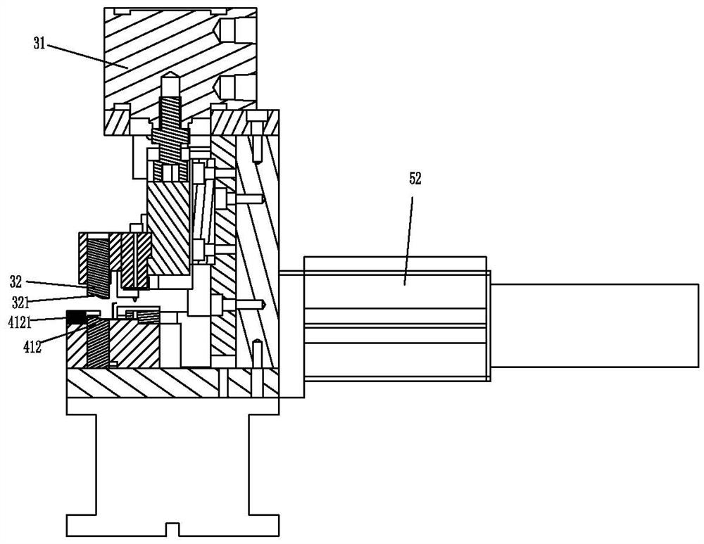
[0062] Please refer to Figure 1 to Figure 15 As shown, it shows the specific structure of the embodiment of the present invention and a terminal strip structure used for cutting.

[0063] Such as figure 1 and figure 2 As shown, a USB terminal cutting device includes a base 10, on which a terminal strip conveying track 40 is arranged; along the conveying direction of the terminal strip conveying track 40, a strip pushing module 20 is sequentially arranged. , Terminal shaping module 30.

[0064] The terminal strip delivery track 40 includes a fixed track 41 and a floating track 42 connected to the delivery end of the fixed track 41; Channel 411; the floating track 42 includes a floating seat 421, and a second channel 422 passing through the floating seat 421 along the conveying direction of the terminal strip conveying track 40, the second channel 422 is connected to the first channel 411, and the The inner bottom surface of the second channel 422 is higher than the inner ...


PUM


Abstract

The invention discloses a USB terminal cutting device which comprises a base, a terminal material belt conveying track, a material belt pushing module and a terminal shaping module. The terminal material belt conveying track comprises a fixed track and a floating track. The inner bottom surface of the second channel of the floating seat is higher than the inner bottom surface of the first channel of the fixed rail; the tail end of the floating track is provided with a terminal cutting and plugging module. The terminal cutting and end inserting module comprises a sliding seat, a first driving unit, a second driving unit, a cutting die and a material receiving plate, the first driving unit can drive the sliding seat to move in the vertical conveying direction, the cutting die is located above the material receiving plate, and the second driving unit can drive the cutting die to move up and down; thus, cutting and terminal insertion are integrated in the same functional module, the device structure is simplified, the occupied space is smaller, clamping and positioning of the terminal group can be completed during cutting, positioning is not needed in the terminal insertion link, terminal insertion accuracy can be ensured, meanwhile, the overall machining and assembling efficiency is effectively improved, and the requirement for higher machining efficiency is better met.

Description

technical field [0001] The invention relates to the field technology of terminal cutting devices, in particular to a USB terminal cutting device. Background technique [0002] The USB terminal is an important part of the USB connector. When the terminal is produced, it is usually in the form of a strip. During the production process, the terminal strip needs to be cut, and the terminal group required for the connector is cut off. Then, the The terminal group is inserted into the rubber core to realize the plug-in operation; usually, the terminal needs to be shaped, so three steps are required: terminal cutting, terminal shaping, and plugging. Correspondingly, three functional modules are required, namely: terminal cutting Cutting module, terminal shaping module, plug-in module, when the terminal cutting module cuts the terminal strip, it uses the blade perpendicular to the length direction of the terminal strip to cut off the material, and then cuts The obtained terminal gr...

Claims


Application Information

Patent Timeline
Patent Type & Authority Applications(China)
IPC IPC(8): B21D28/02B21D28/04B21D28/06B21D28/14B21D43/00B21D43/02B21D3/16H01R43/20H01R43/16
Inventor 韩林黄磊王钰王拥军
Owner FREEPORT GUANGDONG PRECISION IND CO LTD
Learn More