Eureka AIR delivers breakthrough ideas for toughest innovation challenges, trusted by R&D personnel around the world.

Vibration shelling and sand removing device for casting

The technology of a screening device and a movable plate is applied in the field of casting, which can solve the problems of high labor intensity, high noise, and high risk of transportation and placement, and achieve the effects of saving the shelling process and reducing the tendency of cold cracking.

Active Publication Date: 2022-04-12
HUSN CASTING ANHUI YINGLIU GROUP
View PDF12 Cites 0 Cited by
  • Summary
  • Abstract
  • Description
  • Claims
  • Application Information

AI Technical Summary

Problems solved by technology

The existing technology has high labor intensity, high risk of transshipment and placement, high vibration, high noise, and much dust. When the temperature of the module is high, the shelling operation is very dangerous.

Method used


Image

  • Vibration shelling and sand removing device for casting
  • Vibration shelling and sand removing device for casting
  • Vibration shelling and sand removing device for casting

Examples


Embodiment 1

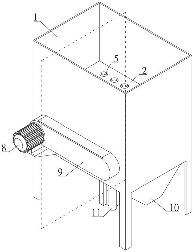
[0032] A casting vibrating dehulling and desanding device includes an outer casing 1 , a collecting box 10 , an upper movable plate 2 , a lower movable plate 4 , a fixed frame 3 and a shelling assembly 6 . The above components are specifically set as follows:

[0033] refer to figure 1 , the outer casing 1 adopts a structure connected up and down, and the outer casing 1 should be made of high temperature resistant materials. In this embodiment, it is a rectangular structure, and a cylindrical structure can also be used.

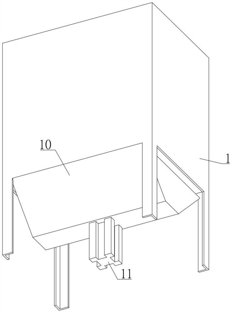
[0034] The collection box 10 is sealed and communicated with the bottom end of the outer casing 1 . A water inlet pipe (not shown) can be installed on the outer shell 1 to add water to the outer shell 1. The collection box 10 is used to collect sandy sewage. sewage.

[0035] There is a gap between the upper movable plate 2 and the lower movable plate 4, and the upper movable plate 2 and the lower movable plate 4 are fixedly connected.

[0036] In this emb...

Embodiment 2

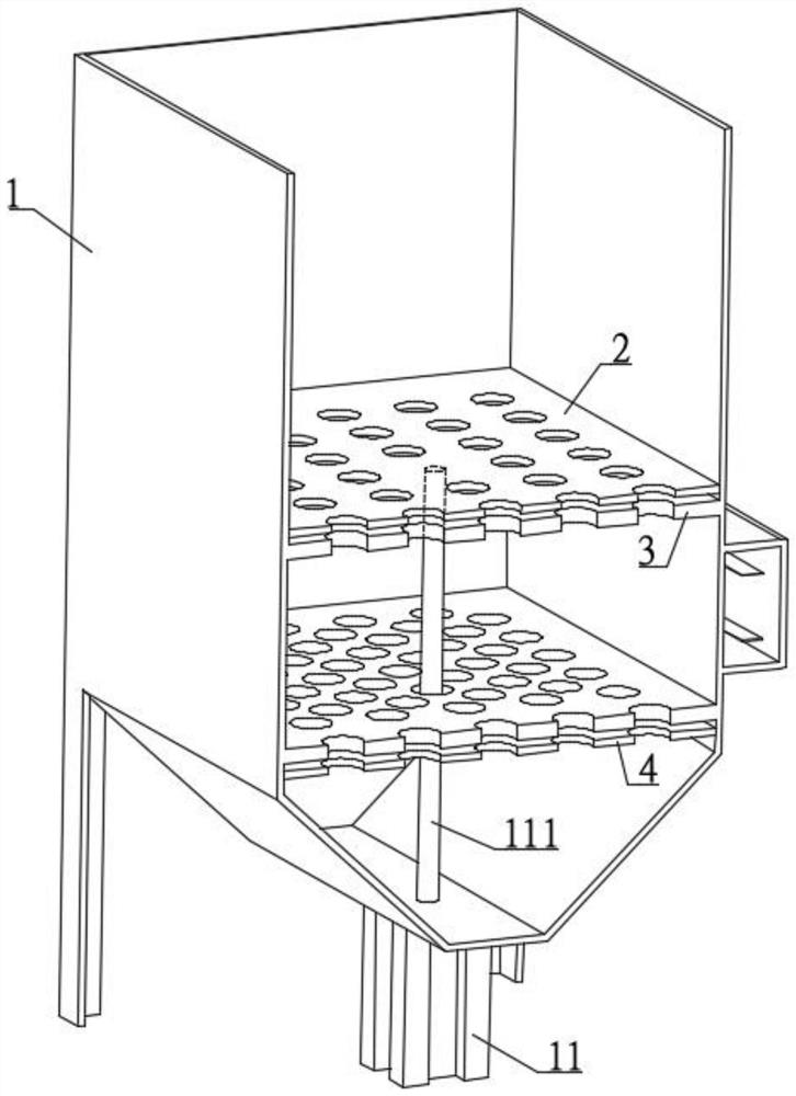
[0054] refer to image 3 The difference between the present embodiment and the first embodiment is that there is a sliding relationship between the upper movable plate 2, the lower movable plate 4 and the housing 1, and also includes the cylinder 11, as follows:

[0055] refer to image 3 , Cylinder 11 is vertically installed on the collection box 10, and the piston rod 111 of cylinder 11 passes through upper movable plate 2, lower movable plate 4 and fixed frame 3, and is fixedly connected with upper movable plate 2 and lower movable plate 4.

[0056]When the cylinder 11 drives the piston rod 111 to move upwards, it drives the upper movable plate 2 and the lower movable plate 4 to move upwards, and the top piece 61 in the shelling assembly 6 cannot be separated from the opening 5 of the lower movable plate 4 when it moves. Specifically, it means that the lower top piece 61 cannot be disengaged from the lower opening 5 during movement, so that the lower movable plate 4 is sea...


PUM


Abstract

The invention discloses a casting vibration shelling and sand removing device which comprises an outer shell and a collecting box, the outer shell is of an up-down communicating structure, and the collecting box is in sealed connection and communication with the bottom end of the outer shell; a gap is formed between the upper movable plate and the lower movable plate, and the upper movable plate and the lower movable plate are fixedly connected; the fixed frame is located in a gap between the upper movable plate and the lower movable plate, and the fixed frame is welded to the inner wall of the outer shell. Opening holes are formed in the corresponding positions of the upper movable plate, the lower movable plate and the fixed frame in an array mode, and additional opening holes are formed in the fixed frame. The shelling assembly is arranged in the fixing frame, and the shelling assembly penetrates through an opening in the upper side of the shelling assembly to be used for shelling. Through vibration shelling in water, on one hand, cooling can be achieved, on the other hand, through the chilling effect of water and the effect that dust is blended into water to form Newtonian fluid, shelling can be achieved through smaller vibration, and the cold crack tendency generated by vibration of special materials can be reduced.

Description

technical field [0001] The invention relates to the technical field of casting, in particular to a vibration shelling and sanding device for casting. Background technique [0002] The existing casting vibration shelling method is to cool the mold shell to below 500°C after pouring, hook the module through the driving hook, hoist it to the vibrating machine, and then manually lift the small part on the vibrating table, or directly hoist it to the large part of the vibrating table . After manual straightening, it is shaken mechanically, and then the shell is shaken and then transported to the pallet for small pieces to be manually transported by driving. The existing technology has high labor intensity, high risk of transshipment and placement, high vibration, high noise, and a lot of dust, and the shelling operation is very dangerous when the temperature of the module is high. Contents of the invention [0003] The object of the present invention is to solve the above-men...

Claims


Application Information

Patent Timeline
Patent Type & Authority Applications(China)
IPC IPC(8): B22D29/02
Inventor 雷伦林郭延普徐丽徐晓娜杜应流张年玉胡存友朱景秀
Owner HUSN CASTING ANHUI YINGLIU GROUP
Why Eureka
Eureka Blog
Learn More