Bar chamfering robot system and method

A robot system and robot body technology, applied in the field of bar chamfering robot system, can solve the problems of large dependence on bending degree and end face inclination, reduce work efficiency, and large amount of chamfering, so as to improve the quality of chamfering, Improve work efficiency, the effect of simple feeding mechanism

Pending Publication Date: 2022-04-12
TAIYUAN UNIVERSITY OF SCIENCE AND TECHNOLOGY +1
View PDF10 Cites 0 Cited by
  • Summary
  • Abstract
  • Description
  • Claims
  • Application Information

AI Technical Summary

Problems solved by technology

However, there are still many deficiencies in this method: 1) Since the length of the spiral groove or thread is not variable, the number of rotations of different diameter rods on the roller is different, the number of rotations of large diameter rods is small, and the amount of chamfering is insufficient; The number of rotations of the material is large, and the amount of chamfering is large
2) The bar may not be able to rotate normally due to insufficient friction between the surface and the spiral conveying roller table, resulting in that the circumferential edges and corners of the end face cannot be ground
3) Only one end of the bar can be chamfered in one operation. When the bar needs to be chamfered at both ends, the position of the bar must be readjusted, and the other end of the bar should be in contact with the chamfering machine. The operation is inconvenient, time-consuming and laborious, and reduces the work efficiency
4) The chamfering effect is highly dependent on the bending degree and end face slope of the incoming bar. If the incoming material is in good condition, the quality of the chamfering will be good; if the incoming material is in poor condition, the quality of the chamfering will be poor.

Method used


Image

  • Bar chamfering robot system and method
  • Bar chamfering robot system and method
  • Bar chamfering robot system and method

Examples


Embodiment Construction

[0032] In order to express the purpose, features and advantages of the patent of the present invention more clearly, the specific implementation of the patent of the present invention will be described in detail below in conjunction with the accompanying drawings.

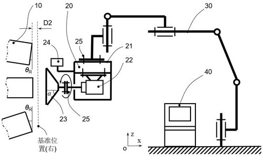
[0033] Such as figure 1 As shown, a bar chamfering robot system and method includes an end effector 20 , a robot body 30 , a control system 40 and a position sensor 50 . The end effector 20 includes a fixed frame 21, a driving motor 22, a grinding head 23 and an industrial camera 24. The fixed frame 21 is connected to the end of the robot body 30 through a bolt 25, and the driving motor 22 is connected to the fixed frame through a bolt 25. 21, the industrial camera 24 is connected to the fixed frame 21 through a special fixture, and the robot body 30 is a six-degree-of-freedom robot.

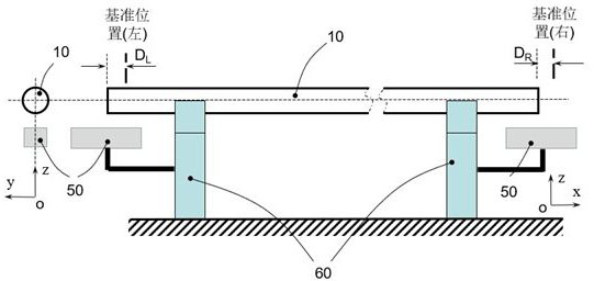
[0034] Such as figure 2 As shown, the bar position sensor 50 is arranged directly under the left and right ends of the bar 10, a...


PUM


Abstract

The invention relates to a bar chamfering robot system and method, chamfering is carried out in a mode that a bar is fixed and a grinding/cutting tool rotates, and the bar chamfering robot system comprises a robot body, a control system, a position sensor, a fixing frame, a driving motor, a grinding/cutting head and an industrial camera. Firstly, the position sensor obtains deviation values between the two ends of the bar and the reference position, then, the industrial camera obtains an offset angle between the end face of the bar and the vertical plane, and finally, the control system processes the data and controls the posture and the movement distance of the end executor, so that the purpose of bar end face chamfering is achieved. According to the invention, the two end surfaces of the bar can be synchronously and uniformly chamfered in a full circumference manner, the dependence on the bending degree and the end surface cutting inclination of the supplied bar is reduced, and the same set of grinding/cutting head can realize the chamfering operation of the bars with different diameters and the same angle, so that the time and the labor are saved, and the working efficiency and the chamfering quality are improved.

Description

technical field [0001] The invention belongs to the field of bar processing, and in particular relates to a bar chamfering robot system and method. Background technique [0002] After the bar is rolled, sawed or sheared, defects such as flashes, sharp edges, and shearing horseshoes will inevitably appear at both ends of the bar. These flashes and sharp edges may damage the probes of the equipment in the flaw detection process. At the same time, Removing flashes and sharp edges also helps to improve the appearance, quality and use value of the bar. Therefore, defects such as flashes and sharp edges at the end of the bar must be removed. [0003] Most of the existing bar chamfering methods adopt the method of bar axial movement + bar rotation + grinding wheel rotation, that is, the bar rests on the conveying roller table with spiral grooves or raised threads, and along with the spiral conveying roller table Rotation, the bar moves and rotates axially, and when the bar reaches...

Claims


Application Information

Patent Timeline
Patent Type & Authority Applications(China)
IPC IPC(8): B24B9/04B24B27/00B24B41/04B24B47/12B24B49/12B24B51/00
Inventor 马自勇马立峰马立东袁文旭
Owner TAIYUAN UNIVERSITY OF SCIENCE AND TECHNOLOGY
Why Eureka
Try Eureka