Wafer and workbench alignment identification method

A recognition method and workbench technology, applied in the direction of working accessories, fine working devices, manufacturing tools, etc., can solve the problem of not being able to cut out a circle, and achieve the effects of ensuring cutting quality, improving work efficiency, and ensuring processing efficiency

Active Publication Date: 2022-04-12
JIANGSU JCA ELECTRONICS TECH CO LTD
View PDF13 Cites 9 Cited by
  • Summary
  • Abstract
  • Description
  • Claims
  • Application Information

AI Technical Summary

Problems solved by technology

[0003] However, in the actual adjustment, it is difficult to achieve the ideal coaxial state between the wafer and the worktable, which results in: in the subsequent rotation process of the worktable, when the cutter cuts according to the predetermined cutting parameters, the expected circular shape cannot be cut.

Method used

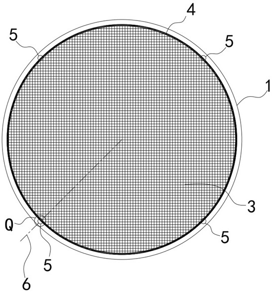
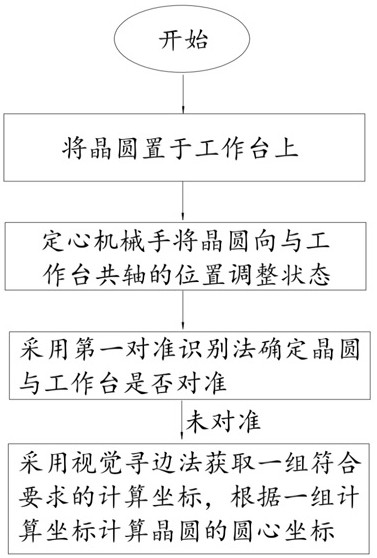
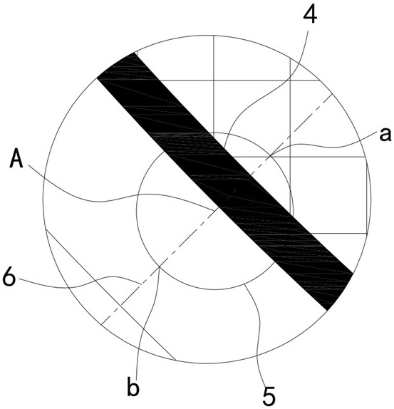

Image

  • Wafer and workbench alignment identification method
  • Wafer and workbench alignment identification method
  • Wafer and workbench alignment identification method

Examples


Embodiment Construction

[0032] Objects, advantages and features of the present invention will be illustrated and explained by the following non-limiting description of preferred embodiments. These embodiments are only typical examples of applying the technical solutions of the present invention, and all technical solutions formed by adopting equivalent replacements or equivalent transformations fall within the protection scope of the present invention.

[0033] In the description of the scheme, it should be noted that the terms "center", "upper", "lower", "left", "right", "front", "rear", "vertical", "horizontal", " The orientation or positional relationship indicated by "inner", "outer", etc. is based on the orientation or positional relationship shown in the drawings, and is only for the convenience of description and simplification of description, rather than indicating or implying that the device or element referred to must have a specific orientation , constructed and operated in a particular or...


PUM


Abstract

The invention discloses a wafer and workbench alignment identification method. The method comprises the following steps: S1, placing a wafer on a workbench; s2, adjusting the wafer to a position coaxial with the workbench through a centering manipulator; and S3, determining whether the wafer is aligned with the workbench by adopting a first alignment identification method, when determining that the workbench is not aligned with the wafer, respectively acquiring a calculation coordinate at each reference hole by adopting a visual edge searching method, and calculating the circle center coordinate of the wafer according to a group of calculation coordinates after acquiring the group of calculation coordinates meeting the requirements. According to the scheme, the first alignment recognition method is adopted firstly, whether the wafer is aligned with the workbench or not can be rapidly determined, the machining efficiency is guaranteed, after alignment failure is rapidly recognized and confirmed, the visual edge searching method is switched to find a set of calculation coordinates, the circle center coordinates of the wafer can be effectively determined, data support is provided for follow-up cutting parameter adjustment, and the machining efficiency is improved. And the cutting quality is ensured.

Description

technical field [0001] The invention relates to the field of wafer processing in semiconductor technology, in particular to a method for identifying the alignment between a wafer and a workbench. Background technique [0002] When cutting the taiko ring on the wafer (the taiko ring and the wafer are coaxial), the wafer is fixed on the worktable, and the worktable rotates to drive the wafer to rotate for cutting. In order to ensure the accuracy of the cut shape of the taiko ring, it is a prerequisite to align the wafer and the table (the table and the wafer are kept in a coaxial state). Therefore, after the wafer is placed on the workbench, a centering manipulator is usually used to adjust the position of the wafer to keep the wafer and the workbench as coaxial as possible. [0003] However, in the actual adjustment, it is difficult to achieve the ideal coaxial state between the wafer and the worktable, which results in: in the subsequent rotation process of the worktable, w...

Claims


Application Information

Patent Timeline
Patent Type & Authority Applications(China)
IPC IPC(8): B28D5/00B28D7/00B28D7/04H01L21/68G06T7/66G06T7/73
Inventor 高金龙张宁宁吕孝袁周鑫蔡国庆
Owner JIANGSU JCA ELECTRONICS TECH CO LTD
Why Eureka
Try Eureka