
Eureka
For R&D, Eureka makes reading and utilizing patents & technical documents easy.
Eureka AIR
Designed for self-driven R&D workflows. Generate viable solutions, solve complex R&D challenges, empower your innovation with AI.

Eureka Materials
Designed for material experts only. Revolutionize your material R&D, from search, analyze, to developing new materials.

TechResearch
Generate reliable direction feasibility study reports for your R&D in just a few steps.

TechSeek
Discover and master advanced knowledge NOW. Basics, ideas, possibilities, all at once.

TechMind
As an expert in R&D Theories, TechMind can generates customized viable solutions instantly.

TechRisk
Analyze your overall solution with one click, know your potential R&D risks in advance.

TechMonitor
Get weekly tech updates, stay abreast of the latest tech innovations and key insights.
Liquid storage bag pipe joint
A liquid storage bag and pipe joint technology, which is applied in the directions of containers, packaging, transportation and packaging, can solve the problems of inconvenient sorting, storage and carrying, and large space occupation, and achieves rapid sorting and storage, reducing space occupation, and convenience. The effect of carrying and transporting
- Summary
- Abstract
- Description
- Claims
- Application Information
AI Technical Summary
Problems solved by technology
Method used
Image

Examples
no. 1 example
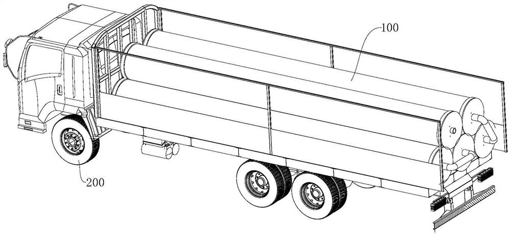
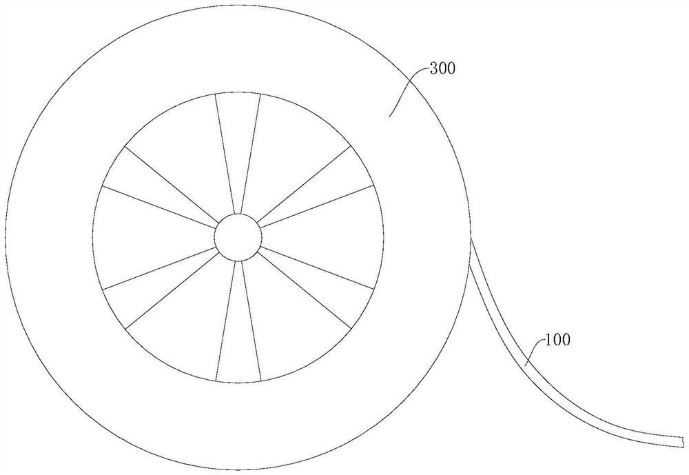
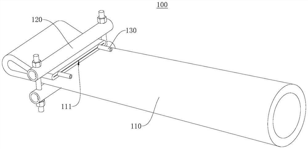
[0033] Please refer to figure 1 , figure 2 and image 3 , the embodiment of the present invention provides a liquid storage bladder tube connector 100 for liquid storage and transportation. It can realize fast liquid storage and liquid supply when in use, and can also realize fast sorting and storage when not in use, reduces occupied space, is easy to carry and transport, and is convenient and practical.
[0034] The reservoir tube connector 100 includes a reservoir tube 110 , a clamping assembly 120 and a connecting tube 130 . The storage bag tube 110 is used to store the storage liquid, and the end of the storage bag tube 110 is provided with an opening 111, and the storage liquid can be injected into the storage bag tube 110 through the opening 111 to realize the liquid storage function, and the storage liquid in the storage bag tube 110 The liquid can be drawn out through the opening 111 to realize the liquid supply function. The clip assembly 120 is detachably mounte...
no. 2 example
[0051] Please refer to Figure 6 , the embodiment of the present invention provides a liquid reservoir tube connector 100, compared with the first embodiment, the difference of this embodiment is that the structure of the clamping assembly 120 is different.
[0052] In this embodiment, the first pressing plate 121 is provided with a first notch 127, the second pressing plate 122 is provided with a second notch 128, and the first notch 127 and the second notch 128 together form a limiting cavity (not shown in the figure), limiting The shape of the bit cavity matches the shape of the connecting tube 130, and the connecting tube 130 is set through the limiting cavity to prevent the first pressing plate 121 and the second pressing plate 122 from crushing the connecting tube 130, and ensure that the connecting tube 130 The storage fluid can flow smoothly.
[0053] Specifically, in the process of installing the clamping assembly 120 and the connecting pipe 130, firstly, the liquid ...
PUM
 Abstract
Description
Claims
Application Information
 - R&D Engineer
- R&D Manager
- IP Professional
- Industry Leading Data Capabilities
- Powerful AI technology
- Patent DNA Extraction
Browse by: Latest US Patents, China's latest patents, Technical Efficacy Thesaurus, Application Domain, Technology Topic, Popular Technical Reports.
© 2024 PatSnap. All rights reserved.Legal|Privacy policy|Modern Slavery Act Transparency Statement|Sitemap|About US| Contact US: help@patsnap.com