Environment-friendly drainage channel for municipal engineering
An environmentally friendly, drainage channel technology, applied in drainage structures, water supply devices, waterway systems, etc., can solve the problems of unfavorable use and promotion, pollution of the surrounding environment, long municipal roads, etc., and achieve the expansion of water collection and drainage. Effect
- Summary
- Abstract
- Description
- Claims
- Application Information
AI Technical Summary
Problems solved by technology
Method used
Image
Examples
Embodiment 1
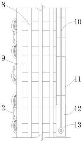
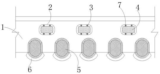
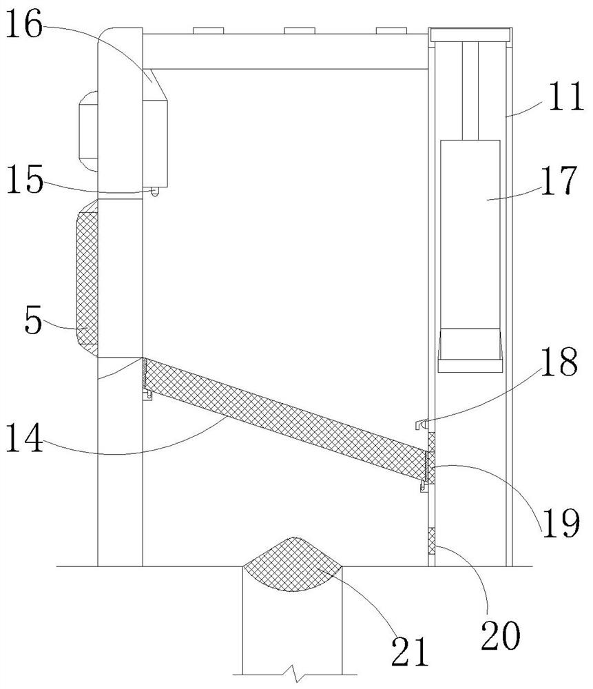
[0035] Such as Figure 1 to Figure 5 As shown, the environment-friendly gutter of the municipal engineering of the present embodiment comprises a gutter main body 1, a main water inlet 9 arranged at the top of the gutter main body 1 and a leaky partition 8 installed on the main water inlet 9, and the main water inlet 9 It is a large-scale water inlet that flows from top to bottom. One side surface of the drainage ditch main body 1 is exposed to the road surface. Different from the prior art, only one water inlet is provided for use. The drainage ditch can be applied to road shoulders, bus waiting areas, etc. In the area, the leaking partition 8 is a protective partition, which does not affect the water intake of the main water inlet 9, and the surface of one side of the main body of the drainage ditch 1 is evenly provided with a collection tank 6, which is a concave tank structure based on the ground at the edge of the road. The collection tank 6 extends to the inside of the d...
Embodiment 2
[0043] The structure of the environmentally friendly drainage tank of the municipal engineering in this embodiment is basically the same as that of the environmental friendly drainage tank of the municipal engineering in Embodiment 1, the difference is that the cleaning mechanism includes a push plate 13, a clamping movable part, an assembly part and a scraper. Plate 17, the inner movable sleeve of movable ring 36 is connected with linkage rod 37, and the top of linkage rod 37 is movably installed with push plate 13 by twisted shaft part 33, and elastic buckle 27 is installed on the surface of one side of push plate 13, and elastic buckle 27 can be snapped into the inside of the chute 10 to form an elastic limit, the snapping movable part is movably installed on the surface of the linkage rod 37, the assembly part is installed at the bottom of the snapping movable part, and the scraper 17 is installed at the bottom of the assembly part (see Figure 6 to Figure 9 ). The push p...
PUM
 Abstract
Description
Claims
Application Information
 - R&D
- Intellectual Property
- Life Sciences
- Materials
- Tech Scout
- Unparalleled Data Quality
- Higher Quality Content
- 60% Fewer Hallucinations
Browse by: Latest US Patents, China's latest patents, Technical Efficacy Thesaurus, Application Domain, Technology Topic, Popular Technical Reports.
© 2025 PatSnap. All rights reserved.Legal|Privacy policy|Modern Slavery Act Transparency Statement|Sitemap|About US| Contact US: help@patsnap.com


