Electric heating device and electric furnace

An electric heating device and heating panel technology, applied in electric heating fuel, ohmic resistance heating parts, lighting and heating equipment, etc., can solve the problems of poor interchangeability, troublesome assembly, different wire lengths, etc.

Pending Publication Date: 2022-04-12
中山市信轩堂文化产业投资有限公司
View PDF1 Cites 0 Cited by
  • Summary
  • Abstract
  • Description
  • Claims
  • Application Information

AI Technical Summary

Problems solved by technology

[0005] The existing movement connection is generally to connect a section of power supply wire and detection wire with the power connection part of the heating element and the temperature measurement element respectively as a terminal. Clamped or welded together, and the wire needs to be connected to fix the movement, which is troublesome to assemble. The wire lengths of different specifications of the shell are different, resulting in the need to customize different terminals for different specifications of the shell, and the interchangeability is poor.

Method used


Image

  • Electric heating device and electric furnace
  • Electric heating device and electric furnace
  • Electric heating device and electric furnace

Examples


Embodiment 1

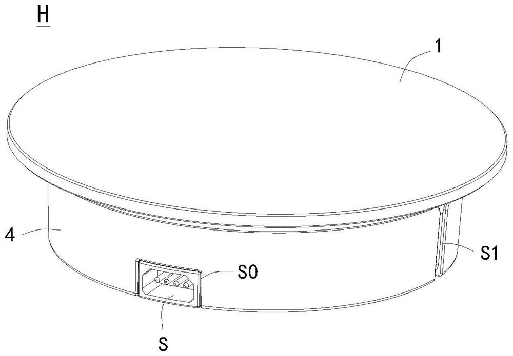
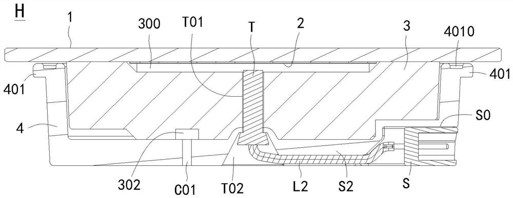
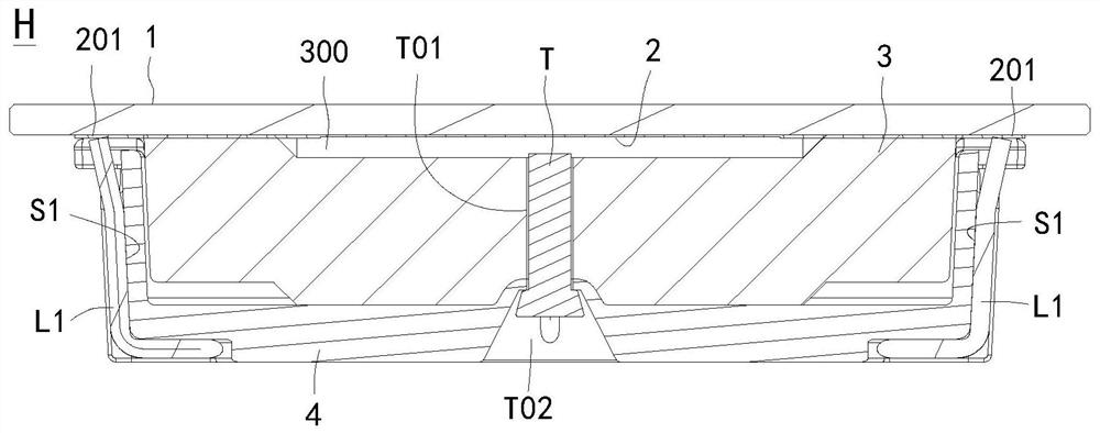
[0050] see Figure 1 to Figure 4 , an electric heating device H, including a heating panel 1, a heating element 2, a heat insulating part 3, a fixed shell 4 and a socket S; The thermal component 3 is provided with a heat insulation cavity 300 with an upper opening for covering the heating element 2, and the fixed shell 4 is provided with a shell cavity 400 with an upper opening for accommodating the heat insulating component 3. The upper end of the fixed shell 4 is glued The bonding material is connected to the heating panel 1, thereby fixing the heat insulating component 3 on the lower side of the heating element 2, and the socket S is electrically connected to the electric connection part 201 through the power supply wire L1. The adhesive material is usually a well-known adhesive material commonly used in electronic components, such as electronic silicone.

[0051] In order to detect the temperature of the heating element 2, a temperature measuring element T is further incl...

Embodiment 2

[0077] see Figure 1 to Figure 14 , Figure 18 , what this embodiment describes is the electric furnace of application embodiment 1 scheme, comprises casing 55, electric heating device H and electric wire assembly (not shown); The opening 501 of the cavity 500 is provided with an assembly step 5011, and the side of the casing 5 is provided with a wire hole 502; the installation and positioning part of the electric heating device H is installed on the upper side of the assembly step 5011; The plug is electrically connected to the socket S through the wire hole 502, and the power line and the detection line are generally packaged in a cable.

[0078] Since the socket S is set on the fixed shell 4 of the electric heating device H, when assembled to the casing 5, the electric wire assembly can be quickly connected to the socket S of the electric heating device H through the plug, and the design space of the external line length is large, and it is interchangeable. Good sex.

[...

Embodiment 3

[0086] see Figure 1 to Figure 14 , Figure 19 , the description of this embodiment is another electric furnace applying the scheme of Embodiment 1, including a casing 5, an electric heating device H, a connecting ring 7 and an electrical lead assembly (not shown); the casing 5 is provided with an upper opening 501 The furnace chamber 500 is provided with an assembly step 5011 around the opening 501 of the furnace chamber 500, and the side of the casing 5 is provided with a wire hole 502; the connecting ring 7 includes a ring wall 701 inserted into the opening 501 of the furnace chamber 500, and the ring is arranged on the The card edge 702 outside the upper end of the ring wall 701, the ring wall 701 connecting the ring 7 is inserted into the opening 501 of the furnace cavity 500, the card edge 702 is fixed on the assembly step 5011, the electric heating device H is assembled in the ring wall 701, and the electric heating The installation and positioning part of the device H...


PUM


Abstract

The electric heating device comprises a heating panel, a heating element, a heat insulation part, a fixing shell, a temperature measuring element and a socket. The heating element is arranged on the lower side of the heating panel and is provided with a power connection part; the heat insulation part is provided with a heat insulation cavity which is opened on the upper side and used for covering the heating element; the fixed shell is provided with a shell cavity which is provided with an opening in the upper side and used for containing the heat insulation component, and the upper end of the fixed shell is connected with the heating panel through a bonding material; the temperature-measuring element is mounted at the bottom of the heat-insulating part; the socket is fixedly connected to the side portion of the fixing shell and electrically connected with the power connection portion and the temperature measuring element through a power supply wire and a detection wire, the power supply wire is arranged in the power supply wire groove, the detection wire is arranged in the detection wire groove, and the interface end of the socket faces the side portion of the fixing shell. The socket is arranged on the fixing shell, an external circuit can be quickly connected with the socket of the electric heating device through the plug during assembly, the assembly mode is simple, quick and reliable in operation and good in interchangeability, modular packaging is achieved, and the integrity of a product is good.

Description

technical field [0001] The invention relates to the technical field of electric furnaces, in particular to an electric heating device and an electric furnace. Background technique [0002] Electric ceramic stoves currently on the market generally include a casing, a core and a panel. The core includes a heating plate and a base of the core. The panel is arranged on the upper side of the heating plate. When working, the heat generated by the heating element in the heating plate heats the panel, and the panel heats the placed items. Electric ceramic stoves have a wide range of uses, with functions such as boiling water, frying, grilling, hot pot, stir-frying, heating milk, soup, and slow stewing, and are favored by consumers. [0003] The traditional movement does not consider the combination of the heating plate and the panel, resulting in a complex structure of the movement and the casing. The casing needs to be equipped with a bottom plate that can open the casing cavity, ...

Claims


Application Information

Patent Timeline
Patent Type & Authority Applications(China)
IPC IPC(8): F24C7/00F24C7/06H05B3/02
Inventor 彭镜溪
Owner 中山市信轩堂文化产业投资有限公司
Why Eureka
Try Eureka