Driving type wind tunnel test system for simulating actual vibration form of structure

A wind tunnel test and driving technology, which is applied in the field of wind tunnel test, can solve the problems of unseen simulation devices and systems, and the inability of buildings to bend and vibrate, so as to make up for the non-reusable use, save test time, and improve fluency

Active Publication Date: 2022-04-12
WUHAN UNIV
View PDF8 Cites 1 Cited by
  • Summary
  • Abstract
  • Description
  • Claims
  • Application Information

AI Technical Summary

Problems solved by technology

[0006] The current vibration models place the vibration device at the bottom of the wind tunnel. There are many such devices, but the common point is that the vibration source at the bottom drives the rigid model to vibrate in the X or Y axis. The biggest problem is the simulated structural vibration. All are linear, and the simulated buildings cannot bend and vibrate
Moreover, the existing torsional vibration simulates that the top and bottom of the building are twisted at an angle at the same time, which is also inconsistent with the reality, because the foundation connected to the ground of the actual building will not be displaced after being affected by the wind
At present, there is no simulation device and system that can realize the simulation of the actual structural mode shape.

Method used


Image

  • Driving type wind tunnel test system for simulating actual vibration form of structure
  • Driving type wind tunnel test system for simulating actual vibration form of structure
  • Driving type wind tunnel test system for simulating actual vibration form of structure

Examples


Embodiment Construction

[0040] The present invention will be further described below in conjunction with the accompanying drawings and specific embodiments, so that those skilled in the art can better understand the present invention, and the examples given are not intended to limit the present invention.

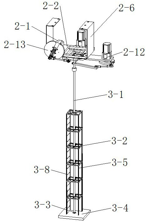
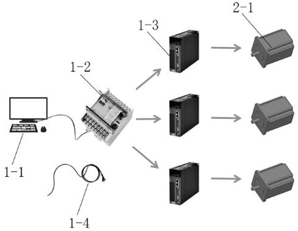
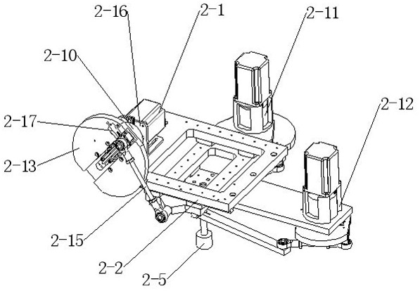
[0041] like figure 1 As shown, the present invention includes three major parts: a numerical control circuit assembly, a driving vibration assembly and a multi-degree-of-freedom structural assembly. The numerical control circuit component is the input end and the output end, which mainly controls the movement of the driving vibration component under a certain set test condition; the driving vibration component can complete the horizontal X, Y and Z under the drive of the motor by relying on the mechanical structure shown. Synchronous and asynchronous movement in the torsional direction, the amplitude, frequency, phase, switch, etc. in all directions can be adjusted by numerical control; the multi-...


PUM


Abstract

The invention provides a driving type wind tunnel test system for simulating the actual vibration form of a structure. The driving type wind tunnel test system comprises a numerical control circuit assembly, a driving type vibration assembly and a multi-degree-of-freedom structure assembly. The numerical control circuit assembly comprises a circuit controller and a motor driver, the motor driver receives an instruction of the controller and controls a servo motor in the driving type vibration assembly to rotate, the driving type vibration assembly is connected with a numerical control circuit, and the driving type vibration assembly comprises the servo motor and a three-way bottom plate. The servo motor drives the three-direction bottom plate assembly to vibrate in the X direction, the Y direction and the Z direction. And the lower part of the three-way bottom plate is connected with the multi-degree-of-freedom structure assembly and drives the multi-degree-of-freedom structure assembly to perform three-degree The wind tunnel test system realizes amplitude-modulated, frequency-modulated and phase-modulated structural three-direction vibration, successfully simulates a nonlinear vibration form which is closer to reality under a driving device, improves the simulation precision, ensures the test result, and can better test important mechanical data such as fluid wind pressure and torsional force of a building structure.

Description

technical field [0001] The invention relates to the technical field of wind tunnel testing, in particular, it is a driving wind tunnel testing system for simulating the actual vibration form of structures, which can be used to test mechanical data such as fluid wind pressure and torsional force of building structures. Background technique [0002] With the development of economic construction, population expansion and shortage of land resources, more and more high-rise buildings are erected. High-rise buildings have the structural characteristics of light weight, low frequency and small damping, and wind loads often become the controlling loads in the design of such structures. Wind-induced structural vibration and glass curtain wall damage accidents occur frequently, so the accurate grasp of the wind-induced effect of high-rise buildings is the key point. At present, the most effective method is to analyze the characteristics of the structural wind-induced response through ...

Claims


Application Information

Patent Timeline
Patent Type & Authority Applications(China)
IPC IPC(8): G01M9/08G01M9/04
CPCY02T90/00
Inventor 樊星妍邹良浩宋杰余敏
Owner WUHAN UNIV
Why Eureka
Try Eureka