Contact method concrete expansion and shrinkage detection device and method based on laser ranging
A technology of laser distance measurement and expansion and contraction, which is applied in the direction of measuring devices, optical devices, material inspection products, etc., can solve the problem of inability to use, limited use environment, and inability to ensure that the central axis of the concrete test piece is in the same direction as the central axis of the dial gauge. Problems such as inside the vertical plane to achieve the effect of improving accuracy and reducing manual errors
- Summary
- Abstract
- Description
- Claims
- Application Information
AI Technical Summary
Problems solved by technology
Method used
Image


Examples
Embodiment 1
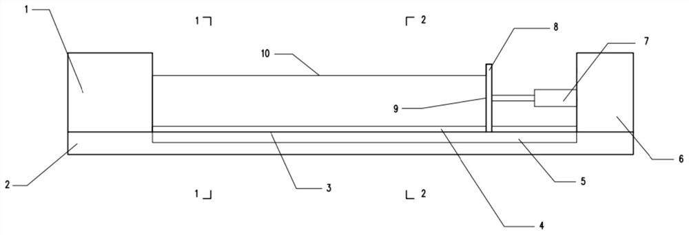
[0029] In the technical solutions disclosed in one or more embodiments, such as Figure 1-6 As shown, the contact method concrete expansion and contraction detection device based on laser distance measurement includes a base 2, a laser distance measurement component arranged on the base 2, a driving mechanism and a correction mechanism; the driving mechanism is arranged on the base opposite to the laser distance measurement component 2, a space for placing the test piece is formed, and the driving mechanism is used to realize the clamping of the test piece; the correction mechanism is arranged along the setting direction of the test piece.
[0030] In this embodiment, the driving mechanism and the laser distance measuring component are arranged on the base 2 opposite to each other to form a fixed space for placing the test piece, which can ensure that the position of the test piece is the same every time, and the position does not need to be corrected every time, which reduces ...
Embodiment 2
[0061] Based on the detection device of embodiment 1, this embodiment provides a method for detecting concrete expansion and contraction by contact method based on laser ranging, including the following steps:
[0062] Step 1. Enter the calibration mode after startup, and control the sliding baffle 8 to the set position A according to the benchmark obtained after calibration;
[0063] Step 2, put the test piece into the placement space on the test device, control the brake motor 6 to drive the push rod 7 to move, push the baffle 8 to move to the laser emitting device 11, until the pressure signal is obtained, and the drive motor 6 stops;
[0064] Step 3, control the laser emitting device 11 to emit laser light, and calculate the distance according to the received reflected light;
[0065] Step 4. Calculate the average value of the distance, which is the length data of the test piece. Return the baffle 8 to the set position. If the baffle reaches position A accurately, continue...
PUM
 Abstract
Description
Claims
Application Information