
Insulation protection method

A technology of insulation protection and protective film, applied in the direction of testing dielectric strength, etc., to avoid partial discharge and achieve the effect of excellent dielectric strength

Pending Publication Date: 2022-04-12
BEIJING SATELLITE MFG FACTORY
View PDF7 Cites 0 Cited by
  • Summary
  • Abstract
  • Description
  • Claims
  • Application Information

AI Technical Summary

Problems solved by technology

However, there is no specific practice of applying parylene vacuum deposition technology to the insulation protection of high-voltage power module products in the prior art

Method used


Image

  • Insulation protection method
  • Insulation protection method

Examples


Embodiment Construction

[0031] In order to more clearly describe the embodiments of the present invention or the technical solutions in the prior art, the following will briefly introduce the drawings that are used in the embodiments. Apparently, the drawings in the following description are only some embodiments of the present invention, and those skilled in the art can also obtain other drawings according to these drawings without creative efforts.

[0032] The present invention will be described in detail below in conjunction with the accompanying drawings and specific embodiments, and the embodiments cannot be repeated here one by one, but the embodiments of the present invention are not therefore limited to the following embodiments.

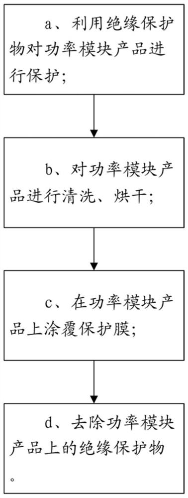
[0033] see figure 1 , the insulation protection method for (military) high-voltage power module of the present invention can be applied to electronic assembly technology to solve problems such as partial discharge of high-voltage power modules. The method mainly ...


PUM


Abstract

The invention relates to an insulation protection method, which comprises the following steps of: a, protecting a power module product by using an insulation protection object; b, cleaning and drying the power module product; c, coating a protective film on the power module product; and d, removing an insulation protection object on the power module product. According to the invention, the partial discharge phenomenon of the module can be avoided, and the requirements of module high-voltage application conditions can be met.

Description

technical field [0001] The invention relates to an insulation protection method. Background technique [0002] High-voltage power modules have the advantages of easy driving, fast control speed, low on-state voltage, large on-state current, and small size. They are the core components of automatic control and are widely used in electric vehicles, home appliances, wind power generation equipment, and solar power generation equipment. And rail transit traction. Existing high-voltage power modules are represented by insulated gate bipolar transistors (IGBTs) and intelligent power modules (IPMs). The main structure of the power module is to solder the chip on the copper-clad ceramic substrate (DBC), and then solder the DBC to the base plate connected to the heat sink. The material of the ceramic substrate is generally Al 2 o 3 Or AlN, which has good thermal conductivity and electrical insulation. During installation, the electrodes of the chip are led out to the DBC through...

Claims


Application Information

Patent Timeline
Patent Type & Authority Applications(China)
IPC IPC(8): G01R31/12
Inventor 彭聪辉孙晓峰飞景明李松玲向语嫣李炎唐林江李相骏刘丹丹张明华陈雅容张彬彬
Owner BEIJING SATELLITE MFG FACTORY
Learn More