Fuel cell thermal management system and control method thereof

A thermal management system and fuel cell technology, applied in the direction of fuel cell heat exchange, fuel cells, fuel cell additives, etc., can solve the problem of increasing the amount of coolant used, complex control systems, affecting the service life of parts and ride comfort, etc. problem, to achieve the effect of reducing the overshoot

Pending Publication Date: 2022-04-12
郑州意昂新能源汽车科技有限公司
View PDF13 Cites 4 Cited by
  • Summary
  • Abstract
  • Description
  • Claims
  • Application Information

AI Technical Summary

Problems solved by technology

[0007] The fuel cell thermal management system deionizer proposed by CN109244505A and CN112751062A is located on the branch road between the expansion tank and the radiator of the cooling system. Only when the fuel cell works in a large cycle mode can the work of adsorbing ions be carried out, and the working conditions are limited.
The thermostat can realize the continuous change of the opening degree and maintain a certain intermediate opening degree, but when the thermostat is kept half-open, the small circulation does not participate in cooling, and it mainly relies on the external large circulation to lower the coolant temperature. At this time, the power of the water pump is large, which wastes electricity from fuel cells
[0009] CN112563533A proposes a fuel cell thermal management system and control method, which integrates the water heating system, but its heat exchanger is located on the bypass branch of the radiator of the cooling system, and the heat exchange capacity is limited; its control method is similar to feedforward The basic value of the value is a fixed value, and then the control method used is threshold value triggering, which will cause frequent and drastic changes in working conditions of components such as water pumps, fans, tees, and PTCs, affecting the service life of components and ride comfort
[0010] In the fuel cell thermal management system and control method proposed by CN112208392A, the heat exchanger is similar to a radiator, and there is no independent plumbing pipeline, which leads to limited design of the plumbing system, and greatly increases the amount of coolant used in commercial vehicles; the control object of the control method is Thermostat and electronic fan, the control method is threshold triggering, which will lead to frequent and drastic changes in working conditions
[0011] The thermal management system and method proposed by CN112909308A only considered the cooling needs of the fuel cell itself, and did not consider the needs of the intercooler of the air system and the water heating of the passenger compartment; the control objects were thermostats and fans
[0012] CN112711282A proposes a model-based control algorithm, which requires model linearization and operating point identification, and finally realizes a global feed-forward controller. The control system is relatively abstract and complex, and it is difficult for ordinary R&D personnel to understand, which brings difficulties to the application of the algorithm
[0013] CN112713290A has proposed a kind of fuzzy controller, and the control object is a fan, and formulating fuzzy control rules requires high experience of research and development personnel, the control effect is lagging behind, and the control statement code is also relatively long
Ordinary feedback control, the initial control parameter is set to a fixed value, only to ensure that the basic functions can run, resulting in a large overshoot
Using threshold trigger control will cause frequent and severe changes in working conditions, which will affect the life of components and ride comfort
Some use feed-forward control algorithms, some only consider the cooling system without considering the water heating system, and some use linearization models and working condition identification, resulting in a more complex control system

Method used


Image

  • Fuel cell thermal management system and control method thereof
  • Fuel cell thermal management system and control method thereof
  • Fuel cell thermal management system and control method thereof

Examples


Embodiment Construction

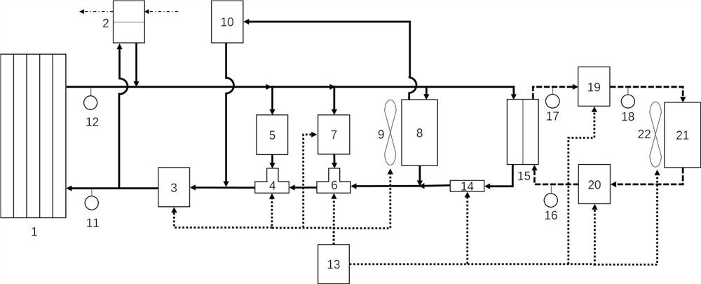
[0045] The following is attached Figure 1-5 The specific implementation manners of the present invention are further described in detail.

[0046] When this embodiment is in use, the circuits include four types: the air circuit of the air system, the cooling liquid circuit of the cooling system, the working medium circuit of the water heating system, and the control signal circuit.

[0047] Heat sources that need to be cooled include electric stacks and air system intercoolers. The air system intercooler is an air circuit on the air system side, and a cooling liquid circuit on the cooling system side.

[0048] The small circulation loop includes electric stack, air system intercooler, water pump, electric control tee, thermostat, cooling system PTC.

[0049] The large circulation circuit includes electric stack, air system intercooler, water pump, electric control tee, thermostat, cooling system radiator, cooling system fan.

[0050] The deionizer circuit includes electric...


PUM


Abstract

According to the fuel cell thermal management system and the control method thereof, the energy utilization rate and the comfort of a passenger compartment are both considered on the premise that the appropriate temperature of the fuel cell is maintained, meanwhile, the water heating system and the cooling system use independent pipelines, the water heating system can be freely arranged, cheaper fluid is selected as a working medium, and the energy consumption is reduced. The deionizer can work at any time according to needs, flow resistance caused when the deionizer does not need to work is avoided, on the basis that a cooling system and a water heating system are comprehensively considered, the working condition is divided into a plurality of sub-working conditions, the working condition in starting is open-loop control, rapid temperature rising is achieved, and the working condition in normal operation is closed-loop control. According to the method, in particular, feedforward and feedback combined control is adopted, an initial control parameter is not simply set as a fixed value any more, a variable feedforward value is determined according to working conditions, and therefore the overshoot is more accurately reduced.

Description

technical field [0001] The invention relates to the technical field of automobiles, in particular to a fuel cell thermal management system and a control method thereof. Background technique [0002] Fuel cells have a series of advantages, such as hydrogen can be obtained by using clean energy to generate electricity and then electrolyze water. The degradation of battery performance is small, and waste heat can be used to heat the passenger compartment to improve comfort. In particular, fuel cell commercial vehicles, which have low requirements for the volume of the hydrogen storage system, relatively fixed driving routes, are easy to meet the demand for hydrogen refueling, and are easy to supervise for safety issues, have obvious advantages in the cold north. The fuel cell also has a series of disadvantages. Too low temperature will affect the electrochemical reaction activity. The proton exchange membrane, the main part of the fuel cell, must have a certain humidity to con...

Claims


Application Information

Patent Timeline
Patent Type & Authority Applications(China)
IPC IPC(8): H01M8/04701H01M8/04007H01M8/04014H01M8/04029
CPCY02E60/50
Inventor 史国军张乐李永刚赵凯旋王蕾
Owner 郑州意昂新能源汽车科技有限公司
Why Eureka
Try Eureka