T-type cable terminal test connector

A technology of cable terminals and connectors, which is applied in the direction of connection, parts of connection devices, devices for joining/disconnecting parts, etc. It can solve the problems of small contact area, weak fixation, poor contact, etc., and achieve safe and reliable connection , Quick disassembly, avoid falling off effect

Active Publication Date: 2022-04-12
PINGDINGSHAN POWER SUPPLY ELECTRIC POWER OF HENAN +1
View PDF15 Cites 0 Cited by
  • Summary
  • Abstract
  • Description
  • Claims
  • Application Information

AI Technical Summary

Problems solved by technology

Although the invention mentions that the cable terminal is sealed with an insulating base and an insulating sheet, this sealing is only used for insulation protection; meanwhile, the metal rod is a columnar structure with a taper, which passes through the cable terminal The connecting nose is connected to the connecting nose, but the metal rod and the connecting nose are in linear contact, the contact area between the two is too small, and the fixation is not firm, and it is easy to cause safety hazards due to poor contact during the test

Method used


Image

  • T-type cable terminal test connector
  • T-type cable terminal test connector
  • T-type cable terminal test connector

Examples


Embodiment 1

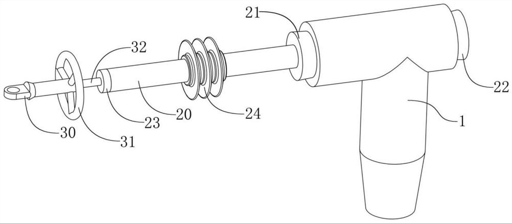
[0052] refer to Figure 1-Figure 2 , the T-shaped cable terminal test connector provided in this embodiment includes a conductive rod 32, and the conductive rod 32 connects from the front port of the cable terminal 1 ( figure 2 The left side in the middle) extends into the connection terminal 11 and is used to lead the cable to the outside of the cable terminal 1, which is convenient for testing the cable.

[0053] The conductive rod 32 is a cylindrical rod, and one end near the connecting terminal 11 is fixedly provided with a conductive sheet 33, the conductive sheet 33 is perpendicular to the conductive rod 32, and is used to fit on the connecting terminal 11, so that the contact between the conductive rod 32 and the connecting terminal 11 The conductive connection is more reliable; one end of the conductive rod 32 away from the terminal 11 is fixedly provided with a test terminal 30 for convenient test connection, and the conductive rod 32 is provided with a voltage equal...

Embodiment 2

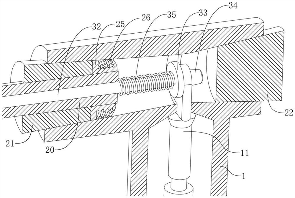
[0068] refer to image 3 Compared with Embodiment 1, the T-shaped cable terminal test connector provided in this embodiment mainly has the following improvements: the conductive rod 32 is threadedly connected with the rear insulating plug 22 .

[0069] Although the conductive rod 32 of Embodiment 1 can be fixed in the cable terminal 1 by the front insulating plug 21, there is still a risk of falling off during the test, so in this embodiment, the conductive rod 32 is screwed to the rear insulating plug 22 , can completely prevent the conductive rod 32 from falling off.

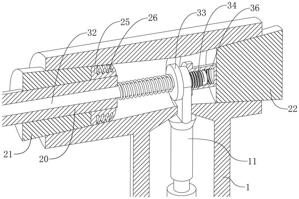
[0070] The positioning seat 34 in this embodiment is a screw structure and is provided with external threads. Correspondingly, a connection seat 36 is fixed vertically at the central position of the side of the rear insulating plug 22 close to the connection terminal 11 , and the connection seat 36 is provided with an internal thread matching the positioning seat 34 . In order to reduce the partial discharge...

Embodiment 3

[0080] refer to Figure 4-6 Compared with Embodiment 2, the T-type cable terminal test connector provided in this embodiment mainly has the following improvements: the conductive rod 32 and the rear insulating plug 22 are quickly connected by pressing and clamping structure.

[0081] Although Embodiment 2 can realize the threaded connection between the conductive rod 32 and the rear insulating plug 22, it needs to be rotated and tightened during the connection, and the operation is cumbersome.

[0082]In this embodiment, the positioning seat 34 is a hollow cylindrical structure, and the connecting seat 36 is also a hollow cylindrical structure. The outer diameter of the positioning seat 34 is slightly smaller than the inner diameter of the connecting seat 36. Meanwhile, the connecting seat 36 is also provided with a positioning rod 37 along the central axis, the outer diameter of the positioning rod 37 is slightly smaller than the inner diameter of the positioning seat 34, and...


PUM


Abstract

The invention provides a T-shaped cable terminal test connector, and belongs to the technical field of electric power operation and maintenance. Comprising a conducting rod, an insulating rod, a front insulating plug and a rear insulating plug, one end of the conducting rod is provided with a test terminal, and the other end of the conducting rod is provided with a conducting strip which is attached to the wiring terminal; a positioning seat is arranged on one side, close to the wiring terminal, of the conducting strip, is of a truncated cone structure and is coaxially arranged with the conducting rod; the insulating rod is a hollow cylindrical rod and sleeves the conducting rod, and the conducting rod is in clearance fit with the insulating rod; the front insulation plug and the rear insulation plug are both of truncated cone structures and are used for plugging the front port and the rear port of the cable terminal. The insulating rod and the front insulating plug are coaxially and fixedly arranged, and the insulating rod penetrates through the front insulating plug; the conducting rod is further sleeved with a first spring, and the first spring is located between the insulating rod and the conducting strip. According to the invention, under the condition that the cable terminal is not dismounted, fault searching or testing of the cable can be realized, the testing effect can be ensured, and the power supply safety is ensured.

Description

technical field [0001] The invention belongs to the technical field of electric power operation and maintenance, and in particular relates to a T-shaped cable terminal test connector. Background technique [0002] The T-type cable terminal is in the shape of a "T", and is mostly used for the incoming and outgoing line terminals of the ring network switch cabinet, and is connected with the incoming and outgoing line bushing seat of the switch cabinet, the wall bushing of the cable branch box, and the double-way bushing with bolts, and is also suitable for Box-type substation devices are widely used in power systems at present. One end of the T-shaped cable terminal installation cable is provided with a semi-conductive layer. [0003] When performing fault finding and testing tests on cables with T-shaped cable terminals, because the cable conductor is inside the T-shaped cable terminal, if the terminal shell is not removed, improper operation during fault finding and test pr...

Claims


Application Information

Patent Timeline
Patent Type & Authority Applications(China)
IPC IPC(8): H01R13/62H01R13/52H01R13/44H01R13/627H01R13/629H01R13/639
Inventor 王得民叶茂张永申张逸群郭营生段发强周伟民孟春晓匡志旭郭继磊郭姚超师亚杰
Owner PINGDINGSHAN POWER SUPPLY ELECTRIC POWER OF HENAN
Why Eureka
Try Eureka