All-optical network communication system and communication method
A communication system and an all-optical network technology, applied in transmission systems, electromagnetic wave transmission systems, instruments, etc., can solve problems such as inability to quickly make targeted countermeasures and low maintenance efficiency, so as to improve maintenance efficiency and avoid malfunctions Judgment, improve the effect of stability
- Summary
- Abstract
- Description
- Claims
- Application Information
AI Technical Summary
Problems solved by technology
Method used
Image
Examples
Embodiment 1
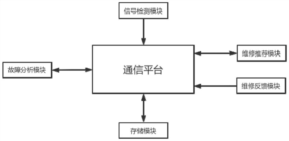
[0040] Such as figure 1 As shown, an all-optical network communication system includes a communication platform and a base station, and the communication platform is connected with a signal detection module, a fault analysis module, a maintenance recommendation module, a maintenance feedback module and a storage module.
[0041] The signal detection module is used to detect and analyze the signal transmission status of each optical fiber node of the communication system. The specific detection and analysis process of the signal transmission status includes: marking the optical fiber node of the communication system as node i, i=1, 2, ... , n, n is a positive integer, obtain the strength value of the signal received by node i and mark it as QDi, obtain the frequency value of the signal received by node i and mark it as PLi, obtain the distortion degree of the signal received by node i and mark it as SZi, by formula The transmission coefficient CSi of node i is obtained. The t...
Embodiment 2
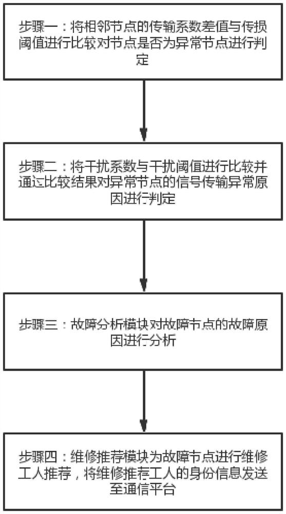
[0058] Such as figure 2 Shown, a kind of all-optical network communication method comprises the following steps:
[0059] Step 1: Calculate the transmission coefficient of the node by calculating the strength value, frequency value and distortion degree of the received signal of the fiber node, and compare the difference between the transmission coefficients of adjacent nodes with the transmission loss threshold to determine whether the node is an abnormal node ;
[0060] Step 2: Perform interference analysis on the abnormal node to obtain the interference coefficient of the abnormal area, compare the interference coefficient with the interference threshold and determine the cause of the abnormal signal transmission of the abnormal node through the comparison result. If the cause of the abnormal signal transmission is regional interference, the The corresponding abnormal node is marked as a normal node; if the cause of the abnormal signal transmission is node failure, the co...
PUM
 Abstract
Description
Claims
Application Information
 - R&D
- Intellectual Property
- Life Sciences
- Materials
- Tech Scout
- Unparalleled Data Quality
- Higher Quality Content
- 60% Fewer Hallucinations
Browse by: Latest US Patents, China's latest patents, Technical Efficacy Thesaurus, Application Domain, Technology Topic, Popular Technical Reports.
© 2025 PatSnap. All rights reserved.Legal|Privacy policy|Modern Slavery Act Transparency Statement|Sitemap|About US| Contact US: help@patsnap.com


