Data control machine tool health monitoring system

A health monitoring system and data control technology, applied in the field of numerical control, can solve problems such as high cost, difficult installation, and no wireless communication module combined with the health monitoring system

Pending Publication Date: 2020-05-12
苏芯物联技术(南京)有限公司
View PDF2 Cites 2 Cited by
  • Summary
  • Abstract
  • Description
  • Claims
  • Application Information

AI Technical Summary

Problems solved by technology

[0004] Wired vibration or acoustic emission acquisition systems are expensive and difficult to install; machine tool health monitoring data stays locally without access to the Internet
Some sensors have reserved wireless communication interfaces and USB interfaces for the monitoring system, but there is no real integration of wireless communication modules into the sensors of the health monitoring system

Method used


Image

  • Data control machine tool health monitoring system
  • Data control machine tool health monitoring system
  • Data control machine tool health monitoring system

Examples


Embodiment 1

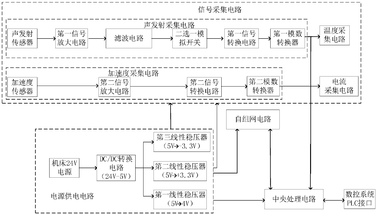
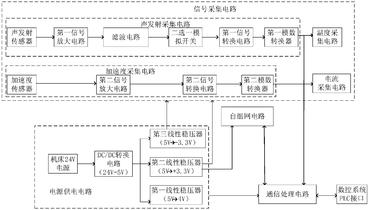
[0044] Such as figure 1 As shown, a data control machine tool health monitoring system, including: power supply circuit, signal acquisition circuit, CNC system PLC interface, ad hoc network circuit, central processing circuit, the power supply circuit, signal acquisition circuit, CNC system PLC interface and the self-organizing network circuit are all connected with the central processing circuit. The central processing circuit is a communication processing circuit.

[0045] More specifically as figure 2 As shown, the power supply circuit includes the machine tool 24V power supply, DC / DC conversion circuit, the first linear voltage regulator, the second linear voltage regulator, the third linear voltage regulator, the machine tool 24V power supply and the input end of the DC / DC conversion circuit connection, the output end of the DC / DC conversion circuit is connected to the input end of the input end of the first linear voltage regulator, the input end of the second linear ...

Embodiment 2

[0067] Embodiment 2: The difference from Embodiment 1 is that the central processing unit selects an ARM processing circuit.

[0068] Such as Figure 10 As shown, a health monitoring system of a numerically controlled machine tool, in this embodiment, there is no need to connect the first linear voltage regulator to supply power to the ARM processing circuit. The ARM processing circuit includes an ARM processor, a memory, and a second reset circuit. The second reset circuit is connected to the ARM processor, and the ARM processor is connected to the memory.

[0069] The power supply circuit, the signal acquisition circuit, the PLC interface of the numerical control system, and the ad hoc network circuit are just that each circuit is connected to the ARM processing circuit. Because the chip changes, the ARM selects the STM32 processor in this embodiment.

[0070] Such as Figure 11 As shown, pins 1, 41, and 42 of the ARM processor are respectively connected to pins 3, 2, and ...


PUM


Abstract

The invention discloses a data control machine tool health monitoring system and relates to the technical field of numerical control, the system comprises a power supply circuit, a signal collection circuit, a numerical control system PLC interface, an ad hoc network circuit and a central processing circuit. Wherein the power supply circuit, the signal collection circuit, the numerical control system PLC interface and the ad hoc network circuit are connected with the central processing circuit, and the power supply circuit is connected with the signal collection circuit, the ad hoc network circuit and the central processing circuit. The method has the advantages that real-time fault diagnosis is carried out on the numerical control machine tool by utilizing a wireless transmission mode andapplying an artificial intelligence technology, and fault early warning is sent out after the fault is detected, so that a manufacturer can quickly position the fault and timely maintain the fault after receiving information, property loss is reduced, and the real-time performance is good.

Description

technical field [0001] The invention relates to the technical field of numerical control, and more specifically relates to a data-controlled machine tool health monitoring system. Background technique [0002] CNC machine tool is a modern electromechanical equipment integrating machine, electricity and fluid. The complexity of CNC technology itself, the diversity of processes and the complexity of processed parts make the specifications of CNC systems diverse, performance differences are large, control parameters are complicated, and debugging operations are cumbersome. Therefore, once the CNC machine tool breaks down, its fault diagnosis and maintenance will be a highly professional work. In many cases, it must rely on the support of the CNC machine tool manufacturer to get the solution. This will cause the faulty machine tool to often not be repaired in time, prolong the downtime of the fault, and reduce the production efficiency of the CNC machine tool. On the other han...

Claims


Application Information

Patent Timeline
Patent Type & Authority Applications(China)
IPC IPC(8): G05B19/401
CPCG05B19/401G05B2219/34242
Inventor 李波石文斌高卉陈海祥聂兰顺杨松贵
Owner 苏芯物联技术(南京)有限公司
Why Eureka
Try Eureka