Delivery aiding device for obstetrics and gynecology department

An obstetrics and gynecology, No. 1 technology, which is applied in the field of obstetrics and gynecology midwifery devices, can solve the problems of unable to grasp the movement range and frequency of the pregnant woman, single limit frame structure, unable to provide guidance for the pregnant woman, etc., so as to correct the fetal position and facilitate delivery. , the effect of reducing fatigue

Inactive Publication Date: 2022-04-15
张常慧
View PDF0 Cites 1 Cited by
  • Summary
  • Abstract
  • Description
  • Claims
  • Application Information

AI Technical Summary

Problems solved by technology

[0002] The doula ball, also known as the delivery ball, is a multifunctional midwifery device. When it is used as a support to support the buttocks of the parturient, the parturient will vibrate up and down or left and right with different frequencies and amplitudes under the guidance of medical staff. The swing can correct the fetal position and promote the labor process, but the current doula ball is only a simple hollow sphere structure, and the puerpera can only rely on the naked eye observation of the medical staff for guidance during the use process, and due to the limitations of the naked eye , so that the medical staff cannot timely grasp the range and frequency of the maternal movement clearly and reasonably, so that they cannot accurately guide the maternal, and then weaken the effect of correcting the fetal position and promoting the labor process, highlighting its shortcomings, and In order to prevent the transitional rolling of the doula ball during use and cannot effectively support the puerpera, it needs to be used with a limiter. However, the traditional limiter has a single structure and limits the rolling range of the doula ball. , can only play a small amount of support for the mother, highlighting its shortcomings

Method used


Image

  • Delivery aiding device for obstetrics and gynecology department
  • Delivery aiding device for obstetrics and gynecology department
  • Delivery aiding device for obstetrics and gynecology department

Examples


Embodiment Construction

[0022] The present invention will be further elaborated below in conjunction with the accompanying drawings and specific embodiments.

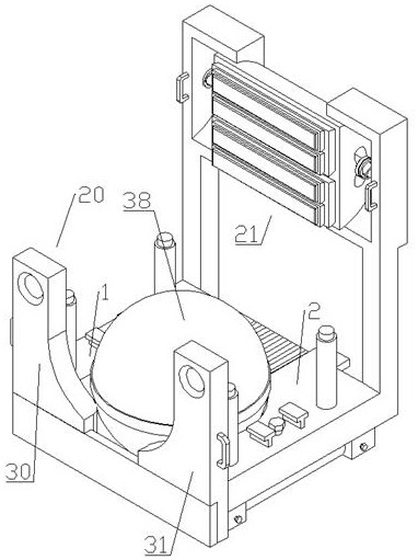
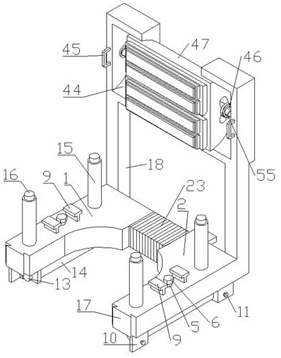
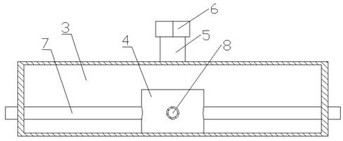
[0023] Such as Figure 1-10As shown, a midwifery device for obstetrics and gynecology, including No. 1 seat 1, No. 2 seat 2, hydraulic oil tank 3, bidirectional variable pump 4, oil injection pipe 5, non-sealed dust cap 6, oil pressure pipe 7, and oil suction pipe 8. Pedal seat 9, support seat 10, adjusting bolt 11, V-shaped clamp block 12, moving roller 13, brake disc 14, piston cylinder 15, piston rod 16, No. 1 dovetail guide rail 17, support frame 18, transmission part 19 , a supporting part 20, a bonding part 21, the first seat 1 and the second seat 2 are hollow inside, and hydraulic oil tanks 3 are respectively fixed inside them, two-way variable variable pumps 4 are respectively fixed inside the two hydraulic oil tanks 3, and Oil injection pipes 5 are respectively fixed at the top, and non-sealed dustproof caps 6 are threadedly connecte...


PUM


Abstract

The midwifery device comprises a first seat, a second seat, a hydraulic oil tank, a two-way variable pump, an oil injection pipe, a non-sealing dustproof cap, an oil pressing pipe, an oil suction pipe, a pedal seat, a supporting seat, an adjusting bolt, a V-shaped clamping block, a moving roller, a brake disc, a piston cylinder, a piston rod, a first dovetail guide rail, a supporting frame, a transmission part, a supporting part and an attaching part. The first base and the second base are hollow, hydraulic oil tanks are fixed in the first base and the second base respectively, two-way variable pumps are fixed in the two hydraulic oil tanks respectively, and oil injection pipes are fixed to the top ends of the two hydraulic oil tanks respectively. The device has the functions of correcting the fetal position, promoting the birth process, facilitating delivery and relieving fatigue at the same time, when the fetal position and the birth process need to be corrected, a puerpera treads on the pedal seat with two feet, then sits at the top end of the music guiding ball and then jumps up and down or swings left and right according to guidance of medical staff, and the puerpera feels comfortable. Therefore, the effects of correcting the fetal position and promoting the birth process are achieved by utilizing the rebound of the guide ball.

Description

technical field [0001] The invention relates to the field of obstetrics and gynecology, in particular to a midwifery device for obstetrics and gynecology. Background technique [0002] The doula ball, also known as the delivery ball, is a multifunctional midwifery device. When it is used as a support to support the buttocks of the parturient, the parturient will vibrate up and down or left and right with different frequencies and amplitudes under the guidance of medical staff. The swing can correct the fetal position and promote the labor process, but the current doula ball is only a simple hollow sphere structure, and the puerpera can only rely on the naked eye observation of the medical staff for guidance during the use process, and due to the limitations of the naked eye , so that the medical staff cannot timely grasp the range and frequency of the maternal movement clearly and reasonably, so that they cannot accurately guide the maternal, and then weaken the effect of co...

Claims


Application Information

Patent Timeline
Patent Type & Authority Applications(China)
IPC IPC(8): A63B23/20
Inventor 张常慧李慎
Owner 张常慧
Why Eureka
Try Eureka