Electric vehicle hub drilling equipment

A technology of drilling equipment and electric vehicles, applied in drilling/drilling equipment, boring/drilling, metal processing equipment, etc., can solve the problems of inability to locate the position of the hub drilling and reducing the efficiency of the hub drilling, etc. To achieve the effect of easy placement, prevent damage, and improve accuracy

Active Publication Date: 2022-04-15
JIANGSU JUN SUPER ELECTRIC CAR ACCESSORIES MFG
View PDF11 Cites 1 Cited by
  • Summary
  • Abstract
  • Description
  • Claims
  • Application Information

AI Technical Summary

Problems solved by technology

[0002] During the processing of the wheel hub, equipment is needed to drill the wheel hub so that the wheel hub can be installed on the electric vehicle. When the existing wheel hub is drilled, the position of the hub needs to be adjusted manually, and the position of the hub cannot be drilled manually. Accurate positioning, and the drilling work of the equipment needs to be stopped when changing the drilling position, which reduces the working efficiency of the equipment for drilling the hub

Method used


Image

  • Electric vehicle hub drilling equipment
  • Electric vehicle hub drilling equipment
  • Electric vehicle hub drilling equipment

Examples


Embodiment 1

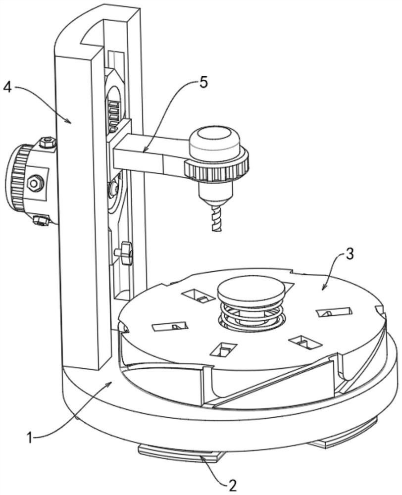
[0036] Please refer to figure 1 , image 3 , Figure 4 , Figure 5 and Figure 8 As shown, an electric wheel hub drilling equipment includes a base 1, the lower surface of the base 1 is fixedly connected with a support block 2, the upper surface of the base 1 is provided with a positioning mechanism 3, and the upper surface of the base 1 is fixedly connected There is a support frame 4, and the inside of the support frame 4 is provided with a drilling mechanism 5.

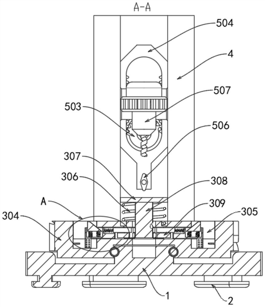
[0037] Positioning mechanism 3 comprises rotating groove 301, first rolling groove 302, ball 303 and rotating body 304, and the upper surface of base 1 is provided with rotating groove 301, and the middle part of rotating groove 301 is provided with first rolling groove 302, and the first rolling groove Balls 303 are rollingly connected to the outer wall of 302 , and a rotating body 304 is connected to the outer side of the balls 303 and close to the inside of the rotating groove 301 for rotation.

[0038]Posit...

Embodiment 2

[0042] Please refer to figure 2 , image 3 and Figure 4 As shown, the positioning mechanism 3 also includes a placement chamber 317, a fixed rod 318, a power cord 319, and a second chute 320. The interior of the movable slot 305 is provided with a placement chamber 317, and the interior of the placement chamber 317 is provided with an electrorheological fluid. The effect of fixing the fixed rod 318, the outer wall of the fixed rod 318 is uniformly provided with several projections, which can effectively improve the effect of friction, the bottom of the movable block 313 and the interior near the placement chamber 317 are fixedly connected with the fixed rod 318, the fixed rod 318 moves inside the placement chamber 317, and the interior of the placement chamber 317 is fixedly connected with a power cord 319, which is electrically connected to the power supply of the equipment. After the power cord 319 is energized, the electrorheological fluid inside the placement chamber 31...

Embodiment 3

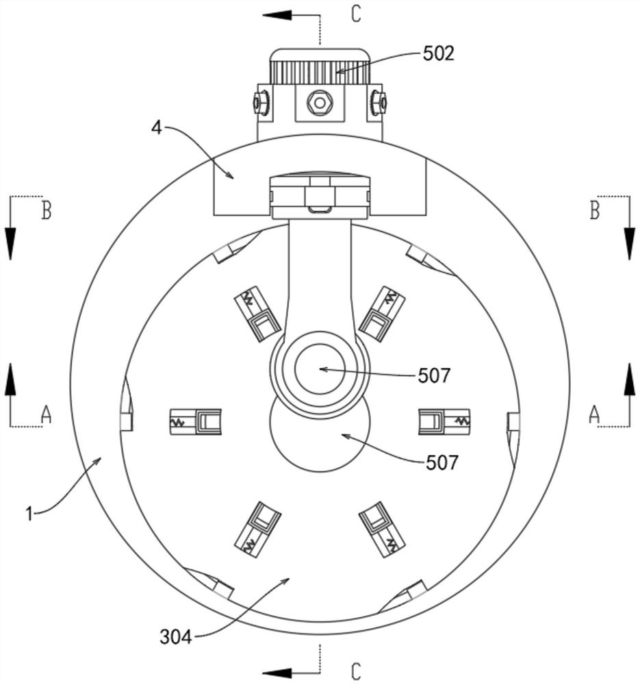
[0045] Please refer to figure 2 , Figure 6 , Figure 7 and Figure 8 As shown, the drilling mechanism 5 includes a second rolling groove 501, a motor 502, a half gear 503, a rack 504, a roller 505, a second positioning block 506 and a drilling device 507, and the inner side of the support frame 4 is provided with a second rolling groove 501, the middle part of the support frame 4 is fixedly connected with a motor 502 by bolts, the motor 502 is electrically connected with the power supply of the equipment, and can drive the half gear 503 to rotate after power on, and the output end of the motor 502 is fixedly connected with the half gear 503, the half gear 503 outside and close to the inside of the support frame 4 is meshed with a gear frame 504, the outside of the gear frame 504 and close to the inside of the second rolling groove 501 is rotatably connected with a roller 505, the outer wall of the roller 505 and the inner wall of the second rolling groove 501 are against e...


PUM


Abstract

The invention discloses electric vehicle hub drilling equipment which comprises a base, a supporting block is fixedly connected to the lower surface of the base, a positioning mechanism is arranged on the upper surface of the base, a supporting frame is fixedly connected to the upper surface of the base, and a drilling mechanism is arranged in the supporting frame. A contact plate drives a threaded rod to move towards the interior of a movable groove, the threaded rod interacts with a rotating plate in the downward moving process to make the rotating plate rotate, a first sliding groove interacts with a sliding rod to make the sliding rod move towards the outer side, and the sliding rod makes a movable block move outwards under the action of a second spring; a movable block drives a first positioning block to move outwards, after the first positioning block moves outwards and cannot make contact with the inner wall of a movable groove, a third spring enables the first positioning block to move upwards, then the hub is positioned, the problem of deviation in the hub drilling process is effectively solved, the hub mounting hole is prevented from deviating, and the service life of the hub is prolonged. And the drilling accuracy of the equipment on the mounting hole is improved.

Description

technical field [0001] The invention relates to the technical field of positioning drilling, in particular to an electric wheel hub drilling equipment. Background technique [0002] During the processing of the wheel hub, equipment is needed to drill the wheel hub so that the wheel hub can be installed on the electric vehicle. When the existing wheel hub is drilled, the position of the hub needs to be adjusted manually, and the position of the hub cannot be drilled manually. Accurate positioning is required, and the drilling work of the equipment needs to be stopped when the drilling position is changed, thereby reducing the working efficiency of the equipment for drilling the hub. [0003] For this reason, propose a kind of electric wheel hub drilling equipment. Contents of the invention [0004] The object of the present invention is to provide an electric wheel hub drilling equipment to solve the problems raised in the background art above. [0005] In order to achiev...

Claims


Application Information

Patent Timeline
Patent Type & Authority Applications(China)
IPC IPC(8): B23B41/00B23B47/20B23Q3/18
CPCB23B41/00B23Q3/18B23Q5/34B23Q2703/10
Inventor 马俊超马彪
Owner JIANGSU JUN SUPER ELECTRIC CAR ACCESSORIES MFG
Why Eureka
Try Eureka