X-ray tube filament welding device and height adjusting method
A technology for an X-ray tube and a welding device, applied in the field of X-ray tubes, can solve the problems of tube current not meeting working requirements, poor laminar flow of electron beams, low electron extraction efficiency, etc., and achieve a wide range of use, simple and reliable structure , to ensure the effect of adjustment stability
- Summary
- Abstract
- Description
- Claims
- Application Information
AI Technical Summary
Problems solved by technology
Method used
Image
Examples
Embodiment 1
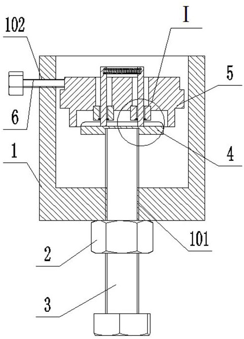
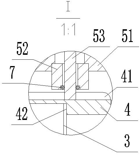
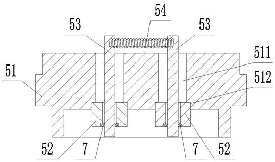
[0044] Such as Figure 1-Figure 5 As shown, an X-ray tube filament welding device includes a sleeve 1, an adjusting bolt 3 and a filament assembly 5, the sleeve 1 includes a side wall and a bottom plate, the center of the bottom plate of the sleeve 1 is provided with a bottom screw hole 101, and the adjusting bolt 3 Connected in the bottom screw hole 101, the filament assembly 5 includes a cathode support seat 51, a filament insulating post 52, a filament lead post 53 and a filament 54, and the cathode support seat 51 is provided with two lead post holes I511; two lead posts Bores I511 are provided with insulating post holes 512. The inner diameter of the insulating post holes 512 is larger than the inner diameter of the lead post holes I511. The two insulating post holes 512 are coaxial with the two lead post holes I511 respectively. Two filament insulating posts 52 are respectively connected in two connected insulating post holes 512, and the filament insulating post 52 is p...
Embodiment 2
[0059] A method for adjusting the height of an X-ray tube filament welding device, comprising the following steps:
[0060] S1. Connect the locking nut 2 to the adjusting bolt 3, screw the adjusting bolt 3 into the bottom screw hole 101, do not tighten the locking nut 2, screw the fixing screw 6 into the side screw hole 102, do not screw the fixing screw 6 into the side screw hole 102 The front end of the screw 6 protrudes from the side wall of the sleeve 1;
[0061] S2. Insert the two filament lead posts 53 into the lead post holes II 521 of the two filament insulation posts 52 respectively, and place pure silver solder wire 7 in the two solder holes 522;
[0062] S3. Put the cathode support seat 51 into the sleeve 1, rotate the cathode support seat 51 so that the two lead post holes I511 are parallel to the groove 41 on the adjustment plate 4, rotate the fixing screw 6 and use the front end of the fixing screw 6 to lock the cathode support seat 51;
[0063] S4. Adjust the ...
PUM
 Abstract
Description
Claims
Application Information
 - R&D
- Intellectual Property
- Life Sciences
- Materials
- Tech Scout
- Unparalleled Data Quality
- Higher Quality Content
- 60% Fewer Hallucinations
Browse by: Latest US Patents, China's latest patents, Technical Efficacy Thesaurus, Application Domain, Technology Topic, Popular Technical Reports.
© 2025 PatSnap. All rights reserved.Legal|Privacy policy|Modern Slavery Act Transparency Statement|Sitemap|About US| Contact US: help@patsnap.com


