
Hanging through type efficient shot blasting machine

A kind of shot blasting machine, high-efficiency technology, applied in the direction of abrasive jetting machine tools, used abrasive processing devices, abrasives, etc., can solve problems affecting shot blasting efficiency, breaking, adjusting shot blasting angle, etc., to improve shot blasting efficiency, Improve versatility and save raw materials

Pending Publication Date: 2022-04-15
潍坊华星机械有限公司
View PDF0 Cites 0 Cited by
  • Summary
  • Abstract
  • Description
  • Claims
  • Application Information

AI Technical Summary

Problems solved by technology

[0004] 1. The used shot is directly transported back to the shot blasting machine through the elevator for reuse, but the shot will be broken and deformed after colliding with the workpiece, and some of the shot does not meet the requirements for use. The existing shot blasting machine cannot remove these The shot material is separated, which affects the shot blasting efficiency;
[0005] 2. The shot blasting device is usually fixed on the outer wall of the shot blasting chamber, and the shot blasting angle cannot be adjusted according to factors such as the size, shape, and position of the workpiece, so the versatility needs to be improved

Method used


Image

  • Hanging through type efficient shot blasting machine
  • Hanging through type efficient shot blasting machine
  • Hanging through type efficient shot blasting machine

Examples


Embodiment Construction

[0034] The following will clearly and completely describe the technical solutions in the embodiments of the present invention with reference to the accompanying drawings in the embodiments of the present invention. Obviously, the described embodiments are only some, not all, embodiments of the present invention.

[0035] It should be noted that all directional indications (such as up, down, left, right, front, back...) in the embodiments of the present invention are only used to explain the relationship between the components in a certain posture (as shown in the accompanying drawings). Relative positional relationship, movement conditions, etc., if the specific posture changes, the directional indication will also change accordingly.

[0036] In addition, the descriptions involving "first", "second" and so on in the present invention are only for descriptive purposes, and should not be understood as indicating or implying their relative importance or implicitly indicating the ...


PUM


Abstract

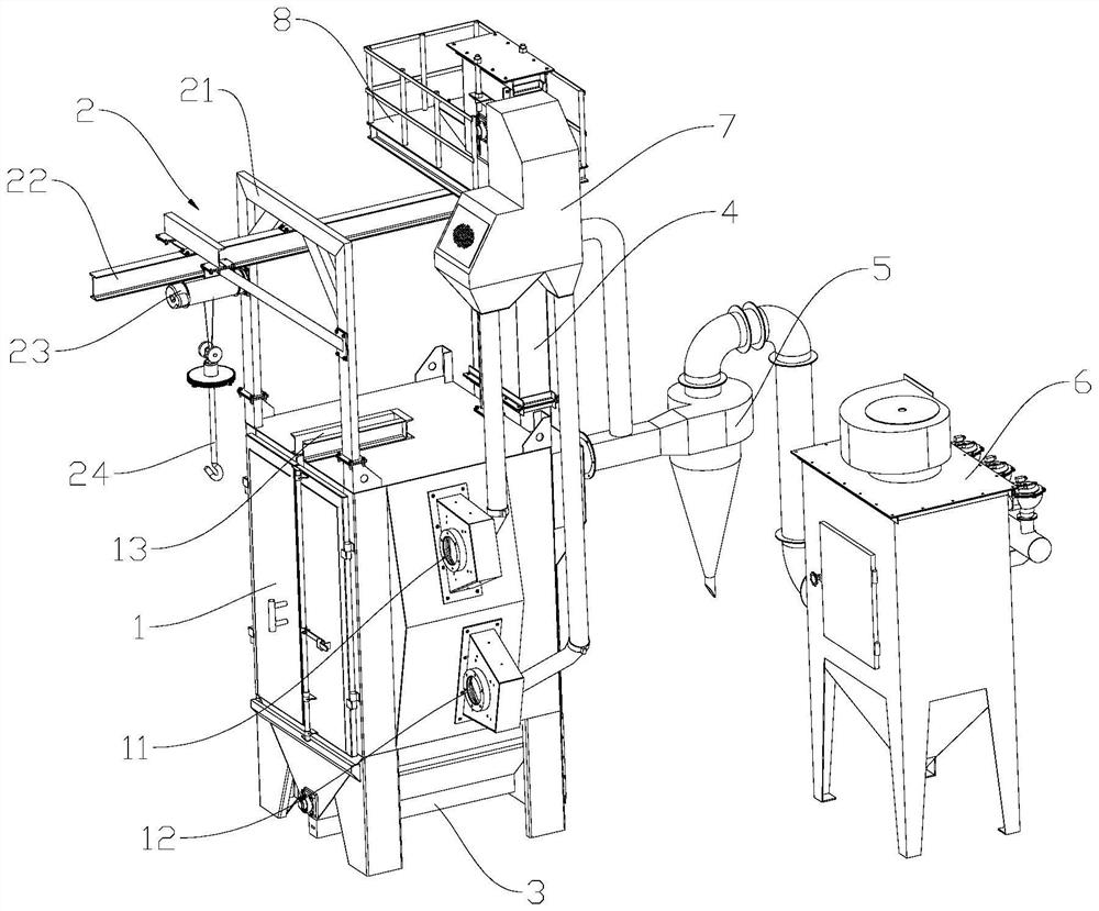
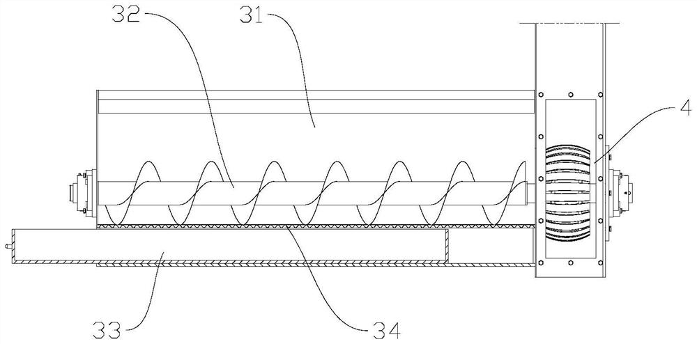
The invention discloses a hanging through type efficient shot blasting machine which comprises a shot blasting chamber, a hanging device, an auger device, an elevator, a cyclone dust collector and a filter cartridge dust collector, the hanging device is arranged above the shot blasting chamber, the auger device is arranged at the bottom of the shot blasting chamber, the elevator is arranged on one side of the shot blasting chamber, and the cyclone dust collector is arranged on the other side of the shot blasting chamber. The cyclone dust collector is respectively connected with the shot blasting chamber and the return box through a dust removal pipeline, the filter cartridge dust collector is connected with the cyclone dust collector through a dust removal pipeline, the auger device comprises a blanking box, an auger and a waste collection drawer, the blanking box is arranged at the bottom of the shot blasting chamber, the auger is transversely arranged in the blanking box, one end of the auger is in synchronous transmission connection with the elevator, and the other end of the auger is in synchronous transmission connection with the waste collection drawer. The waste collecting drawer is arranged at the bottom of the blanking box, and a sieve plate is arranged between the blanking box and the waste collecting drawer. Through cooperation of the auger device and the elevator, used shots can be screened and recycled and conveyed back to the shot blasting device to be reused, raw materials are saved, and the shot blasting efficiency is improved.

Description

technical field [0001] The invention relates to the technical field of shot blasting machines, in particular to a hanging through-type high-efficiency shot blasting machine. Background technique [0002] Hanging type shot blasting machine is also called hook type shot blasting machine or hanging type shot blasting machine. It transports the workpiece into the shot blasting room through the hanging system, and shoots the shot through the shot blaster at high speed to hit the surface of the workpiece. Remove impurities, welding slag or rust spots on the surface of the workpiece, suitable for surface cleaning and strengthening treatment of medium and small castings and forgings in foundry, construction, chemical industry, electrical machinery, machine tools and other industries. [0003] Although the cleaning and strengthening effect of the hanging shot blasting machine is good at present, and it is flexible and convenient to use, there are still the following problems: [000...

Claims


Application Information

Patent Timeline
Patent Type & Authority Applications(China)
IPC IPC(8): B24C1/08B24C3/00B24C9/00
CPCB24C1/083B24C1/086B24C3/00B24C9/006Y02P70/10
Inventor 聂茳泽聂西春郭秀莲刘腾腾王浩张立超
Owner 潍坊华星机械有限公司
Learn More