
Natural gas well fluid separator

A technology of natural gas and separator, which is applied in the direction of production fluid, wellbore/well components, earthwork drilling and production, etc. It can solve the problems that the plunger cannot go down, reduce the lifting efficiency of bottom-hole fluid accumulation, and increase the plunger leakage, etc., and achieve Easy to descend and ensure the effect of lifting efficiency

Pending Publication Date: 2022-04-15
成都百胜野牛科技有限公司
View PDF0 Cites 0 Cited by
  • Summary
  • Abstract
  • Description
  • Claims
  • Application Information

AI Technical Summary

Problems solved by technology

The problem with the above-mentioned plunger is that the plunger may not be able to go down when shutting in the well due to the joint action of fluid resistance and the friction between the sealing gasket and the inner wall of the well.
However, the flow channel through the upper and lower leads to a substantial increase in the leakage when the plunger goes up, which reduces the lifting efficiency of the bottom hole fluid
In some cases, it may also cause the plunger to fail to return to the wellhead, posing a safety hazard

Method used


Image

  • Natural gas well fluid separator
  • Natural gas well fluid separator
  • Natural gas well fluid separator

Examples


Embodiment 1

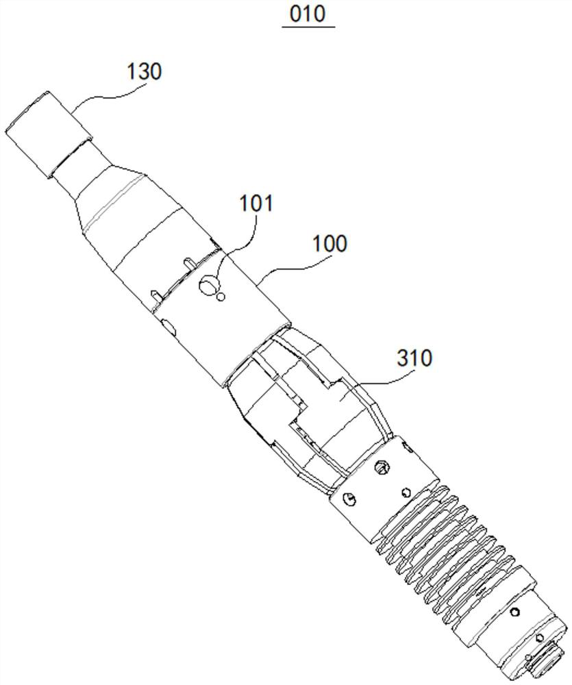
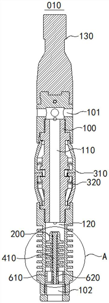
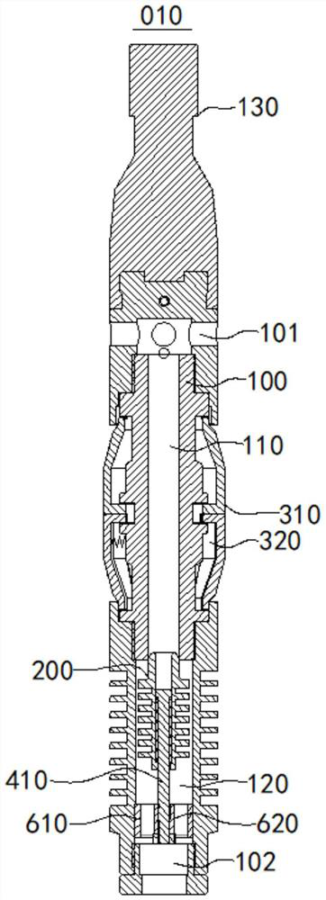
[0039] figure 1 A schematic diagram of the external structure of the natural gas well fluid separator 010 provided in this embodiment. figure 2 A schematic cross-sectional structure diagram of a natural gas well fluid separator 010 provided in this embodiment, in which the plugging column 200 is in an open position. image 3 A schematic cross-sectional structure diagram of a natural gas well fluid separator 010 provided in this embodiment, in which the plugging column 200 is located at the plugging position. Figure 4 yes figure 2 Enlarged view of A.

[0040] Please refer to Figure 1-Figure 4 , the natural gas well fluid separator 010 provided in this embodiment includes a mandrel 100, a plugging column 200 and a circumferential sealing mechanism.

[0041] The two axial ends of the mandrel 100 are respectively provided with an upper flow port 101 and a lower flow port 102 which communicate with the outside world, and along the direction from the upper flow port 101 to t...


PUM


Abstract

The invention relates to the technical field of natural gas extraction, and discloses a natural gas well fluid separator which comprises a mandrel, a plugging column and a circumferential sealing mechanism. An upper circulation opening and a lower circulation opening which are communicated with the outside are formed in the two axial ends of the mandrel respectively, an upper fluid channel and a lower fluid channel which extend in the axial direction of the mandrel are formed in the mandrel, the upper fluid channel and the lower fluid channel are communicated with each other, and the inner diameter of the upper fluid channel is smaller than that of the lower fluid channel. The plugging column is arranged in the lower fluid channel in an axially movable mode and is constructed to do reciprocating motion between a plugging position and an opening position. The circumferential sealing mechanism is arranged around the mandrel. The plugging column is constructed to block communication between the upper fluid channel and the lower fluid channel when the plugging column is located at the plugging position, and the upper fluid channel and the lower fluid channel are communicated with each other when the plugging column leaves the plugging position. According to the natural gas well fluid separator provided by the invention, the lifting efficiency is guaranteed, and meanwhile, the natural gas well fluid separator can descend more easily.

Description

technical field [0001] The present application relates to the technical field of natural gas exploitation, in particular to a fluid separator for a natural gas well. Background technique [0002] During the production of natural gas wells, bottomhole fluid accumulation is an important factor affecting the production of natural gas wells. In order to increase the production of natural gas wells, it is necessary to drain bottomhole fluids from the natural gas wells. [0003] Plunger (also known as fluid divider) drainage is a drainage gas recovery technique. The plunger includes a plurality of sealing gaskets, and these sealing gaskets are in contact with the inner wall of the shaft under the action of the elastic member to form a seal. In the shut-in state, the plunger goes down to the bottom of the well. When the well is opened, the thrust generated by the fluid below the plunger drives the plunger upward, thereby lifting the accumulated fluid above the plunger and discha...

Claims


Application Information

Patent Timeline
IPC IPC(8): E21B43/00
CPCE21B43/121
Inventor 陈满刘书豪刘树飞苏诗策陈俊宏李灵
Owner 成都百胜野牛科技有限公司
Learn More