Supercharge Your Innovation With Domain-Expert AI Agents!

Multi-section continuous drum furnace

A drum furnace, multi-stage technology, applied in the field of heating furnace, can solve the problems of easy backlog of materials discharged from the heating furnace, difficult maintenance, etc., and achieve the effects of saving energy, improving service life, and facilitating discharging

Pending Publication Date: 2022-04-15
江苏新江南炉业科技有限公司
View PDF0 Cites 0 Cited by
  • Summary
  • Abstract
  • Description
  • Claims
  • Application Information

AI Technical Summary

Problems solved by technology

[0004] The purpose of this application is to provide a multi-stage continuous drum furnace in order to solve the problem that the discharge of multiple heating furnaces is easy to backlog and maintenance is difficult.

Method used


Image

  • Multi-section continuous drum furnace
  • Multi-section continuous drum furnace
  • Multi-section continuous drum furnace

Examples


Embodiment 1

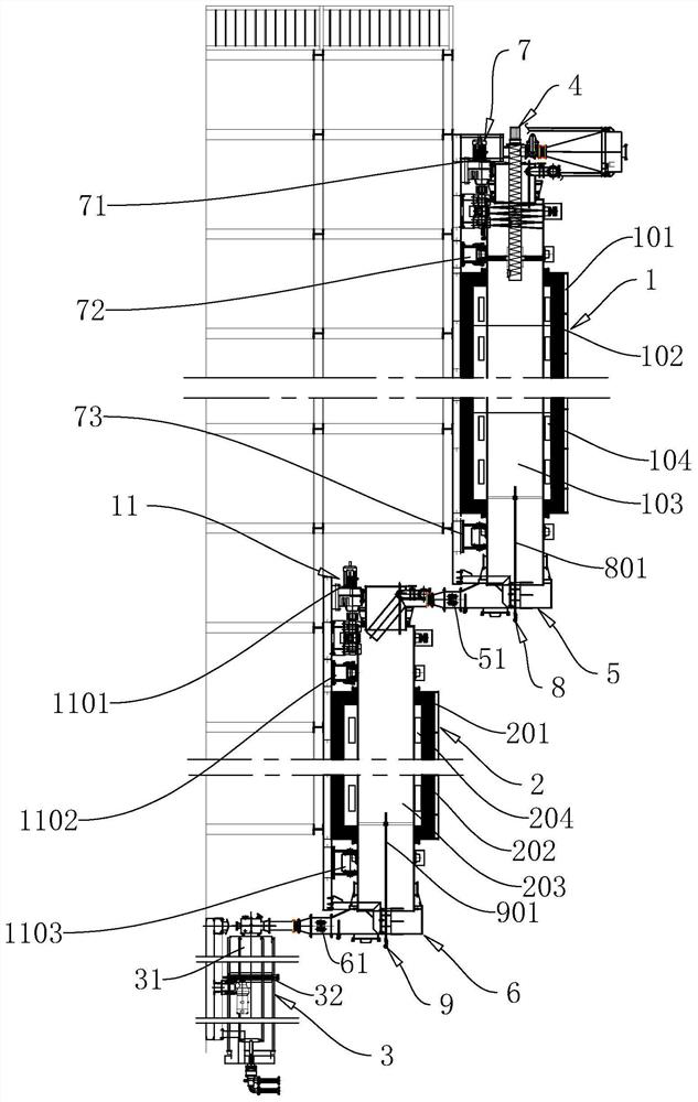
[0042] refer to figure 1 and figure 2 , This embodiment discloses a multi-stage continuous roller furnace. This embodiment adopts a three-stage continuous roller furnace, which includes a low-temperature section furnace body 1 , at least one high-temperature section furnace body 2 and a discharge cooling mechanism 3 . The furnace body 1 in the low-temperature section, the furnace body 2 in the high-temperature section, and the discharge cooling mechanism 3 are arranged in sequence along the length direction. The feed end of the furnace body 1 in the low temperature section is connected with a set of electric screw machine 4, and the electric screw machine 4 is connected with a feed bin for feeding into the furnace body 1 in the low temperature section. The discharge end of the furnace body 1 in the low temperature section is connected to the feed end of the furnace body 2 in the high temperature section through the first collection bin 5, and the discharge end of the furnace...

Embodiment 2

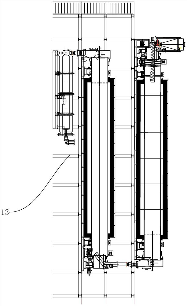
[0061] refer to image 3 , the rest of this embodiment is the same as that of Embodiment 1. The difference is that in order to reduce the requirements for the workshop in production, in this embodiment, a frame 13 is provided, and the frame 13 is a structure of upper and lower layers. In this embodiment, Among them, the furnace body 1 of the low temperature section is installed on the uppermost layer of the frame 13 , the furnace body 2 of the high temperature section is arranged on the middle layer of the frame 13 , and the discharge cooling mechanism 3 is installed on the bottom layer of the frame 13 .

Embodiment 3

[0063] refer to Figure 4 and Figure 5, the rest of this embodiment is the same as Embodiment 1 or Embodiment 2. The difference is that if the low-temperature heating part 104 between the low-temperature furnace shell 101 and the low-temperature drum 103 fails, in order to reduce the time for downtime maintenance, this embodiment Among them, the low temperature heating part 104 is set to the following structure:

[0064] The low-temperature heating part 104 includes a heating seat 1041 and an electric heating wire 1042 arranged on the heating seat 1041. The heating seat 1041 is an annular structure. The inner ring of the heating seat 1041 is also provided with a moving plate 1043, and the moving plate 1043 is coated with a high temperature resistant heat insulating material. Slots 1011 distributed along the axial direction of the low temperature furnace shell 101 are also provided on the low temperature furnace shell 101 ; and guide seats 1012 are provided on the low temper...


PUM


Abstract

The invention discloses a multi-section type continuous roller furnace which comprises at least one low-temperature section furnace body, at least one high-temperature section furnace body and a discharging cooling mechanism. The discharging end of the low-temperature section furnace body is connected with the feeding end of the high-temperature section furnace body, and the discharging end of the high-temperature section furnace body is connected with the discharging cooling mechanism. The discharging end of the low-temperature section furnace body is lower than the feeding end of the low-temperature section furnace body; the low-temperature section furnace body comprises a low-temperature furnace shell, a low-temperature furnace lining, a low-temperature roller and a low-temperature heating assembly. The height of the discharging end of the high-temperature section furnace body is smaller than that of the feeding end of the high-temperature section furnace body. The high-temperature section furnace body comprises a high-temperature furnace shell, a high-temperature furnace lining, a high-temperature roller and a high-temperature heating assembly. According to the device, low-temperature preheating and high-temperature heating operation can be conducted on materials, heat loss can be reduced, the service life of the heating system is prolonged, discharging can be conducted through the self weight of the materials, and then energy is effectively saved.

Description

technical field [0001] The invention relates to a heating furnace, in particular to a multi-stage continuous drum furnace. Background technique [0002] The drum furnace is mainly suitable for heating treatment such as drying, roasting, coating and granulation of battery graphite materials. The drum furnace in the prior art often achieves the drying and roasting of materials through a single furnace body through temperature adjustment, but in the temperature adjustment process, it is often impossible to effectively implement the separation process for processes with different temperature ranges and different operations. The continuous operation of the tank, because it is concentrated in the same tank, often leads to frequent temperature changes, incomplete reactions, and long time-consuming defects. [0003] With the development of technology, split-type drum furnaces have appeared, and materials are heated separately by using low-temperature furnaces and high-temperature f...

Claims


Application Information

Patent Timeline
IPC IPC(8): F27B9/02F27B9/04F27B9/06F27B9/12F27B9/16F27B9/30F27B9/36F27B9/39F27B9/40B01J2/12
Inventor 张志平朱卫国
Owner 江苏新江南炉业科技有限公司
Features
  • R&D
  • Intellectual Property
  • Life Sciences
  • Materials
  • Tech Scout
  • Unparalleled Data Quality
  • Higher Quality Content
  • 60% Fewer Hallucinations
Learn More