Inductor manufacturing method and inductor

A production method and inductor technology, which is applied in the manufacture of inductors/transformers/magnets, circuits, electrical components, etc., can solve problems affecting electrical properties, life-span voltage withstand and structural strength, gaps between cores and powders, and cracks in cores To achieve the effect of improving the magnetic inductance and coil uniformity, increasing the voltage tolerance, preventing coil deformation or damage to the enamelled film

Inactive Publication Date: 2022-04-15
美磊电子科技(昆山)有限公司
View PDF0 Cites 0 Cited by
  • Summary
  • Abstract
  • Description
  • Claims
  • Application Information

AI Technical Summary

Problems solved by technology

[0003] The existing manufacturing methods of inductors are mostly to directly put the core into the coil and then directly form it. The relative angle between the coil and the copper sheet will determine the degree of skewing of the internal coil after forming, and the internal coil will be deformed and squeezed during forming. Aggravate the skew of the coil; there is a gap (internal crack) between the core and the powder; the core has cracks; after placing the core, there is an obvious core outline by X-ray observation, and the competition can judge the production method; the coil is deformed and the paint film is damaged. loss, the above conditions will affect the electrical properties, life, voltage withstand and structural strength. Therefore, the production method of the inductor and the inductor

Method used


Image

  • Inductor manufacturing method and inductor
  • Inductor manufacturing method and inductor
  • Inductor manufacturing method and inductor

Examples


Embodiment 1

[0030] see Figure 1-3 , the present invention provides a technical solution:

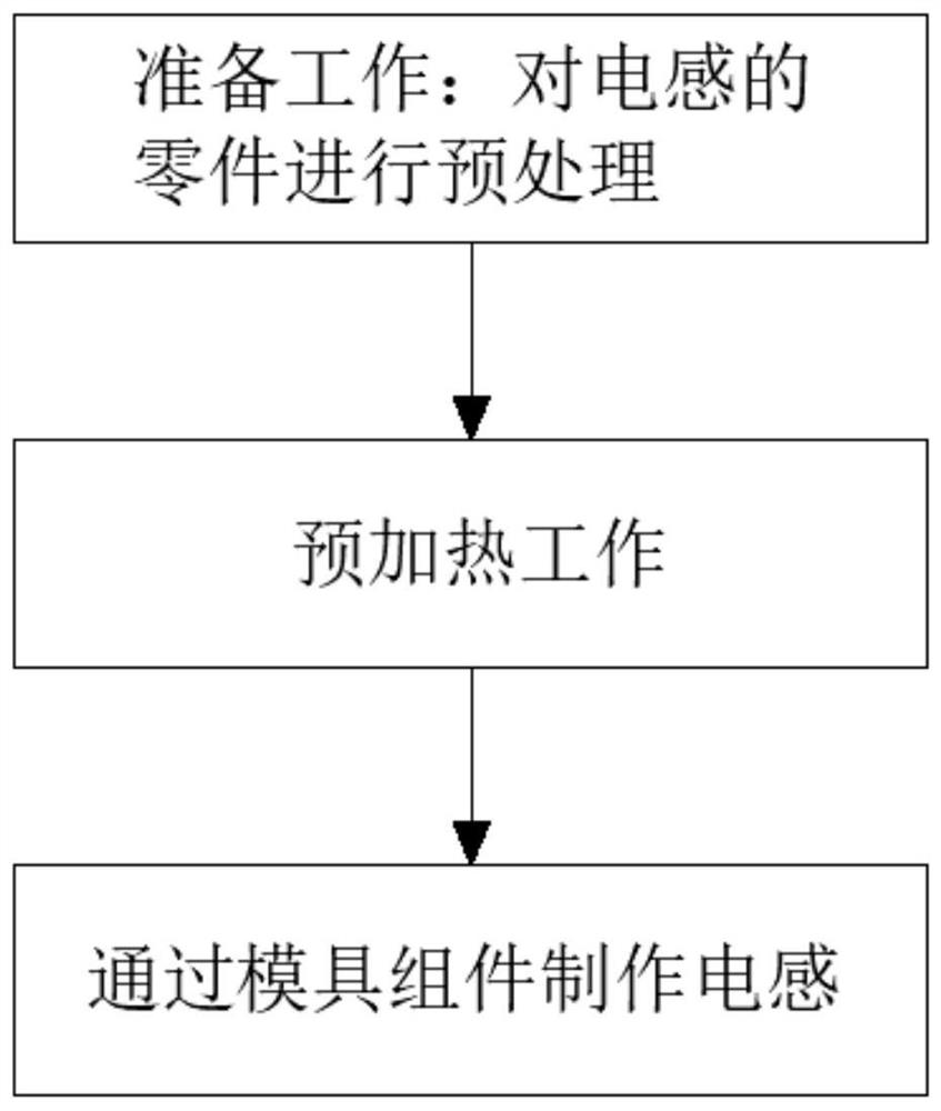
[0031] A method for manufacturing an inductor, comprising the steps of:

[0032] S1. Preparatory work: pre-treat the parts of the inductor. The pre-treatment steps include basic inspection of the parts of the inductor, whether the core 1 is intact, whether there is a crack, and whether the paint film of the coil 3 is intact;

[0033] S2. Preheating work: Preheat the mold components, bake the core body 1, the baking time of the core body 1 is 6-12 hours, and the temperature is 60-200 degrees;

[0034] S3, making inductors through mold components, including the following steps:

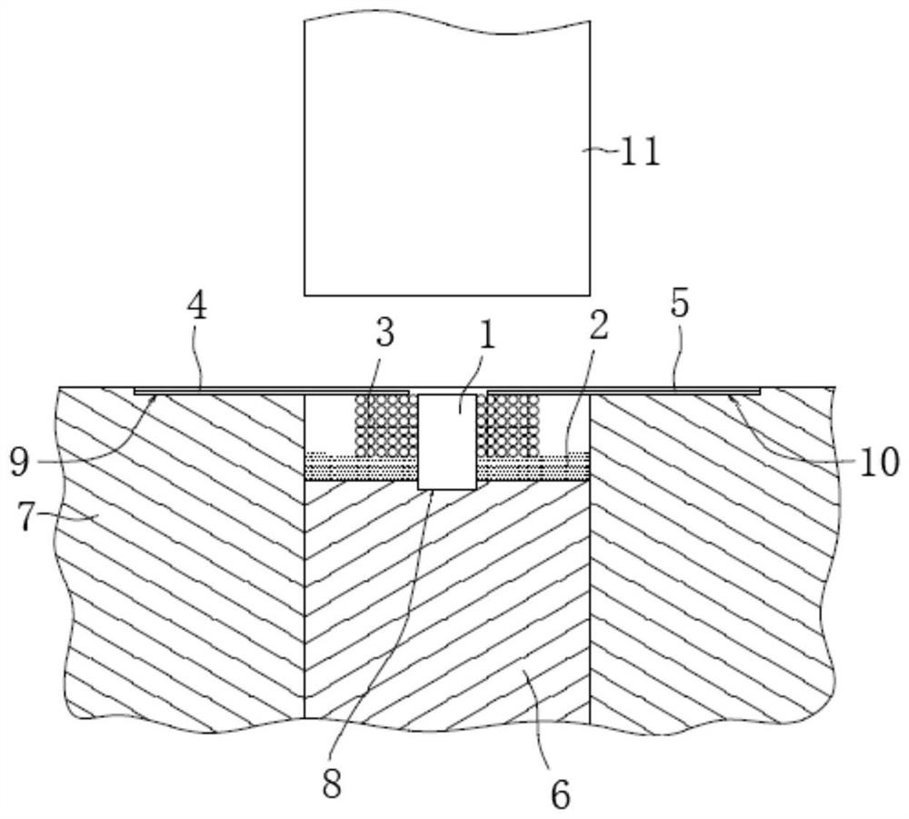
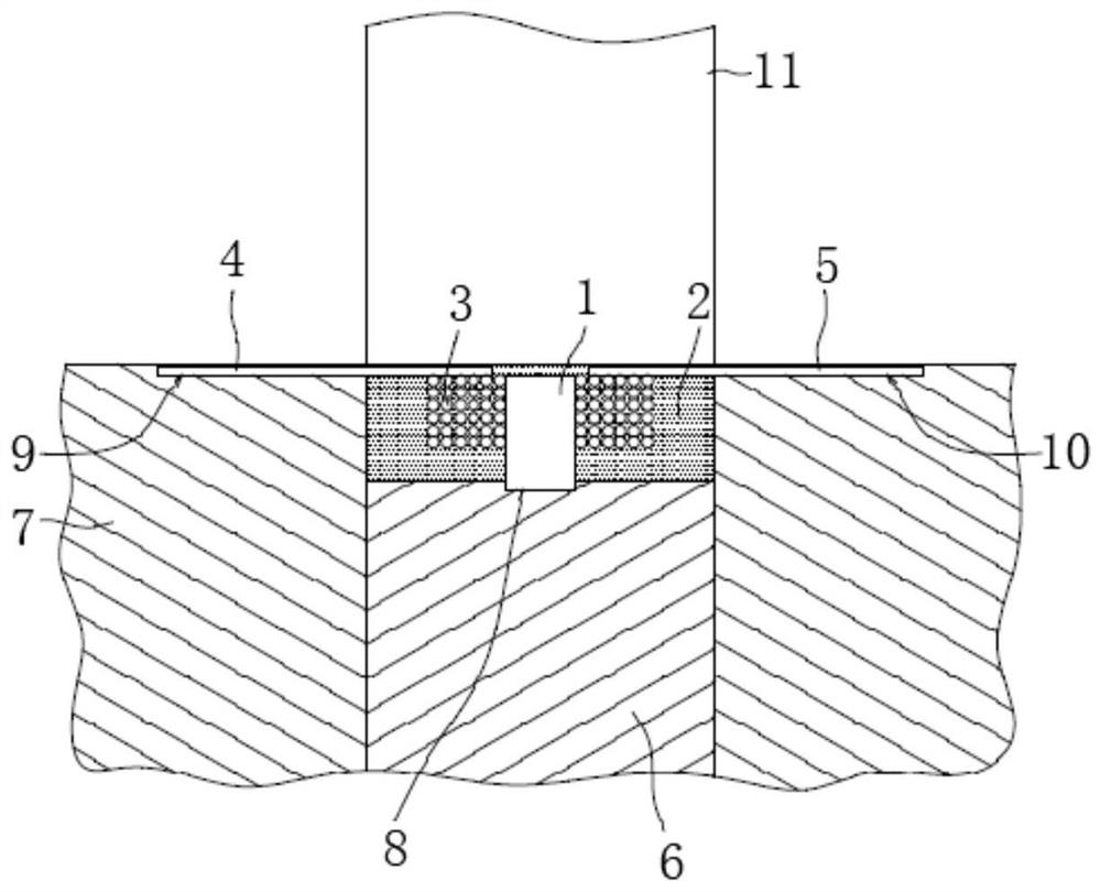
[0035] S3.1. Put the baked core 1 into the mold. The mold assembly includes an upper mold core 11 and a lower mold core 6. The inner bottom wall of the lower mold core 6 is provided with a groove 8, and the outer side of the lower mold core 6 is movable. The lower mold 7 is sleeved, and the top two sides of the lower mold...

Embodiment 2

[0041] The difference between this embodiment 2 and embodiment 1 is:

[0042] A method for manufacturing an inductor, comprising the steps of:

[0043] S1. Preparatory work: pre-treat the parts of the inductor. The pre-treatment steps include basic inspection of the parts of the inductor, whether the core 1 is intact, whether there is a crack, and whether the paint film of the coil 3 is intact;

[0044] S2. Preheating work: Preheat the mold components, bake the core body 1, the baking time of the core body 1 is 6, and the temperature is 60 degrees;

[0045] S3, making inductors through mold components, including the following steps:

[0046] S3.1. Put the baked core 1 into the mold. The mold assembly includes an upper mold core 11 and a lower mold core 6. The inner bottom wall of the lower mold core 6 is provided with a groove 8, and the outer side of the lower mold core 6 is movable. The lower mold 7 is sleeved, and the top two sides of the lower mold core 6 are respectivel...

Embodiment 3

[0051] The difference between this embodiment 3 and embodiment 2 is:

[0052] A method for manufacturing an inductor, comprising the steps of:

[0053] S1. Preparatory work: pre-treat the parts of the inductor. The pre-treatment steps include basic inspection of the parts of the inductor, whether the core 1 is intact, whether there is a crack, and whether the paint film of the coil 3 is intact;

[0054] S2. Preheating work: Preheat the mold components, bake the core body 1, the baking time of the core body 1 is 12 hours, and the temperature is 200 degrees;

[0055] S3, making inductors through mold components, including the following steps:

[0056] S3.1. Put the baked core 1 into the mold. The mold assembly includes an upper mold core 11 and a lower mold core 6. The inner bottom wall of the lower mold core 6 is provided with a groove 8, and the outer side of the lower mold core 6 is movable. The lower mold 7 is sleeved, and the top two sides of the lower mold core 6 are res...


PUM


Abstract

The invention discloses an inductor manufacturing method and an inductor. The preparation work comprises the steps of preprocessing parts of the inductor; preheating work is conducted, specifically, the mold assembly is preheated, and the core body is baked; the method for manufacturing the inductor through the mold assembly comprises the following steps that a baked core body is placed in a mold, and a groove matched with the core body is formed in the inner bottom wall of a lower mold core; the lower mold core is filled with about 1/3 powder, the powder is heated to the set temperature of 60-200 DEG C, and the 1/3 powder is cured and supports the front, rear, left and right positions of the core body and the mold. According to the coil, internal cracks caused by internal stress generated by volatilization or heating of central gas or other compounds are avoided, cracks or gaps of the core body are prevented, the coil can bear pressure during forming due to the fact that the core body has a certain density, and deformation of the coil or damage of a varnished film can be prevented.

Description

technical field [0001] The invention relates to the technical field of inductance production, in particular to an inductance production method and the inductance. Background technique [0002] Inductors can be made of a coiled core of electrically conductive material, typically copper wire, or the core can be removed or replaced with a ferromagnetic material. A core material with a higher magnetic permeability than air can bind the magnetic field more tightly around the inductance element, thus increasing the inductance. The main function of the inductance is to isolate and filter AC signals or form a resonant circuit with capacitors and resistors. . [0003] The existing manufacturing methods of inductors are mostly to directly put the core into the coil and then directly form it. The relative angle between the coil and the copper sheet will determine the degree of skewing of the internal coil after forming, and the internal coil will be deformed and squeezed during formin...

Claims


Application Information

Patent Timeline
Patent Type & Authority Applications(China)
IPC IPC(8): H01F41/00H01F41/02
Inventor 邱昭裕邓铭钦
Owner 美磊电子科技(昆山)有限公司
Why Eureka
Try Eureka