Pressing cylinder structure and laser welding equipment

A technology of laser welding and pressure cylinder, which is applied in laser welding equipment, welding equipment, metal processing equipment, etc., can solve the problems of unsatisfactory welding surface effect, prevent laser power from weakening, reduce excessive welding seam reinforcement, reduce The effect of weld spatter

Pending Publication Date: 2022-04-19
深圳市大族锂电智能装备有限公司
View PDF0 Cites 0 Cited by
  • Summary
  • Abstract
  • Description
  • Claims
  • Application Information

AI Technical Summary

Problems solved by technology

[0003] The purpose of the present invention is to provide a pressure cylinder structure and laser welding equipment to solve the technical problem of unsatisfactory welding surface effect after laser welding of the Busbar of the existing power battery module

Method used


Image

  • Pressing cylinder structure and laser welding equipment
  • Pressing cylinder structure and laser welding equipment
  • Pressing cylinder structure and laser welding equipment

Examples


Embodiment

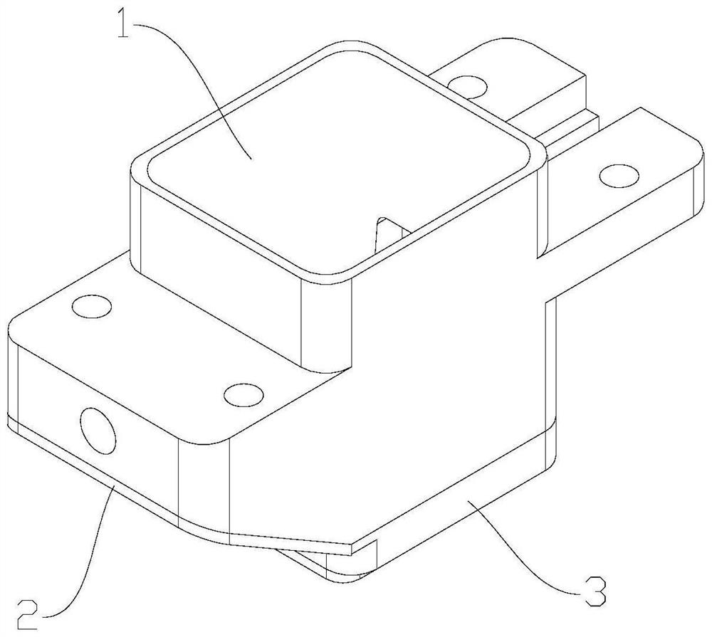
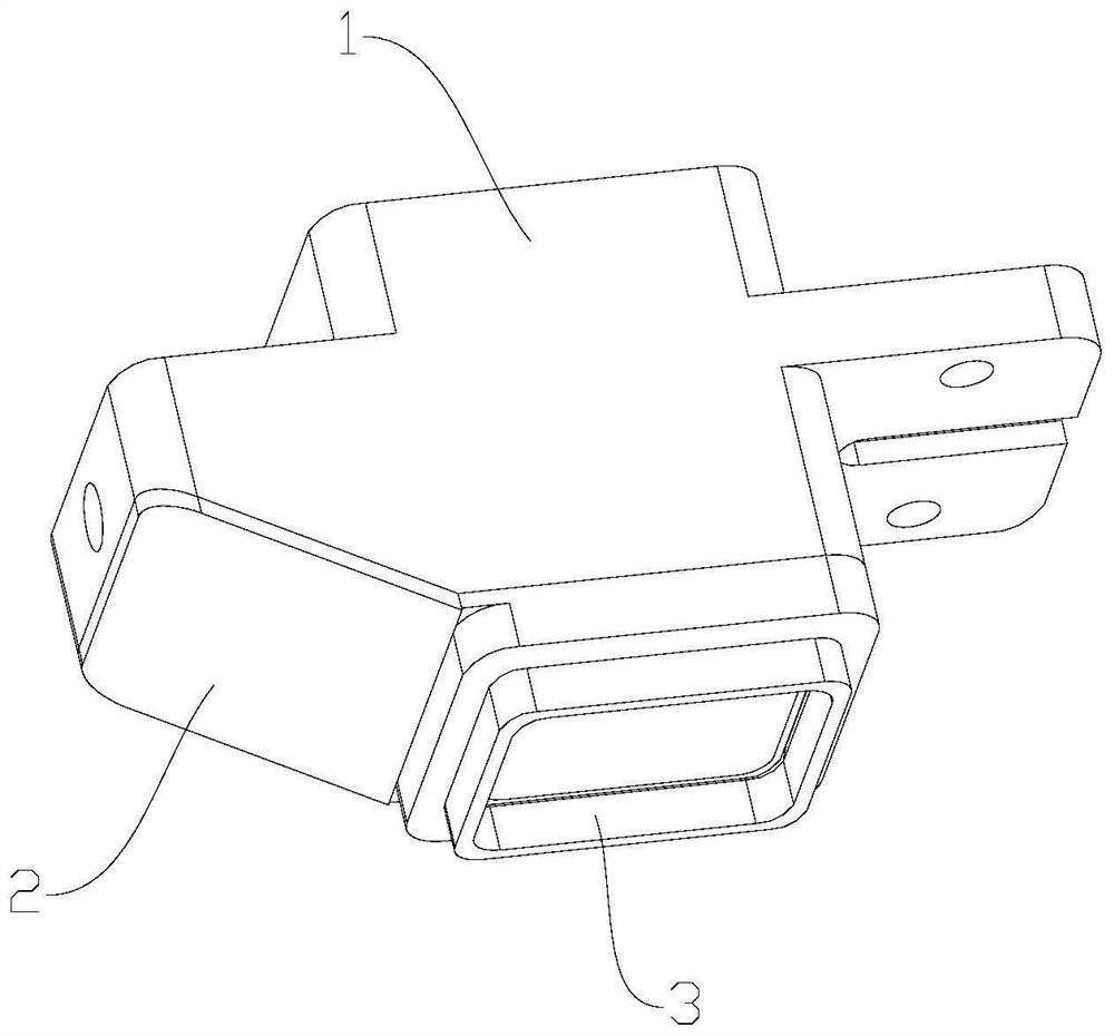
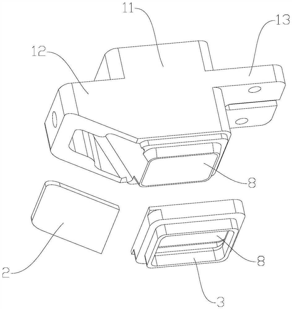
[0046] Such as Figure 1 to Figure 5 As shown, a pressure cylinder structure includes a first pressure cylinder 1, a cover plate 2 and a second pressure cylinder 3;

[0047] The second pressure cylinder 3 is arranged at the bottom of the first pressure cylinder 1, an air inlet 4 is provided on one side of the first pressure cylinder 1, and the cover plate 2 is arranged at the position of the first pressure cylinder 1. One side of the air inlet 4, an air passage 5 is provided between the first pressure cylinder 1, the cover plate 2 and the second pressure cylinder 3, and the air passage 5 communicates with the air inlet 4 and is in the The lower ends of the first pressure cylinder 1 and the second pressure cylinder 3 are formed with an air outlet 6, and the air inlet 4 is used to blow in protective gas, and the protective gas passes through the air channel 5 and is discharged from the air outlet 6. blow out.

[0048] The pressure cylinder structure provided by the embodiment of...


PUM


Abstract

The invention belongs to the technical field of laser welding, and relates to a pressing cylinder structure and laser welding equipment. The laser welding device is applied to laser welding of a power battery module and comprises a first pressing cylinder, a cover plate and a second pressing cylinder. The second pressing cylinder is arranged at the bottom of the first pressing cylinder, an air inlet is formed in one side of the first pressing cylinder, the cover plate is arranged on the side, located on the air inlet, of the first pressing cylinder, and an air channel is formed among the first pressing cylinder, the cover plate and the second pressing cylinder. The air channel is communicated with the air inlet, air outlets are formed in the lower end of the first pressing cylinder and the lower end of the second pressing cylinder, the air inlet is used for blowing in protective gas, and the protective gas passes through the air channel and is blown out of the air outlets. The shielding gas can cover each welding area more uniformly, so that each welding area is protected more comprehensively, the situations that a welding object splashes and the surplus height of a welding seam is too high during welding are well reduced, the welding effect is improved to a great extent, and the welding object is more attractive after being welded.

Description

technical field [0001] The present application relates to the technical field of laser welding, and more specifically, relates to a pressure cylinder structure and laser welding equipment. Background technique [0002] The function of the Busbar (bus bar, bus bar) of the power battery module is mainly to realize the electrical connection between the battery cells. At present, the laser welding of the Busbar of the power battery module generally has unsatisfactory welding surface effects, such as excessive weld reinforcement, severe welding spatter, etc. In order to obtain a good welding effect, the use of a ring spot laser can also make The welding effect has been improved, but the cost of the ring spot laser is much higher than that of the traditional spot laser. Therefore, it is necessary to develop a pressure cylinder structure that attaches the Busbar to the pole of the power battery module and protects the position of the welding seam through shielding gas. Contents ...

Claims


Application Information

Patent Timeline
Patent Type & Authority Applications(China)
IPC IPC(8): B23K26/70B23K26/21B23K26/12B23K26/16
CPCB23K26/70B23K26/21B23K26/123B23K26/16
Inventor 林坤南董建伟高云松高云峰
Owner 深圳市大族锂电智能装备有限公司
Why Eureka
Try Eureka