Runner plate structure

A flow channel plate and pipeline technology, applied in the valve shell structure, functional valve type, lift valve and other directions, can solve the problems of high cost of embedded check valve, leakage of embedded check valve, complicated structure of flow channel plate, etc. Achieve a wide range of applications and scenes, reduce weight, and compact structure

Pending Publication Date: 2022-04-19
ZHEJIANG YINLUN MACHINERY
View PDF9 Cites 0 Cited by
  • Summary
  • Abstract
  • Description
  • Claims
  • Application Information

AI Technical Summary

Problems solved by technology

[0004] However, the structure of the channel plate using the embedded check valve will be more complicated, the cost of the embedded check valve is too high, and the space occupied is too large, and the embedded check valve is prone to leakage

Method used


Image

  • Runner plate structure
  • Runner plate structure

Examples


Embodiment 1

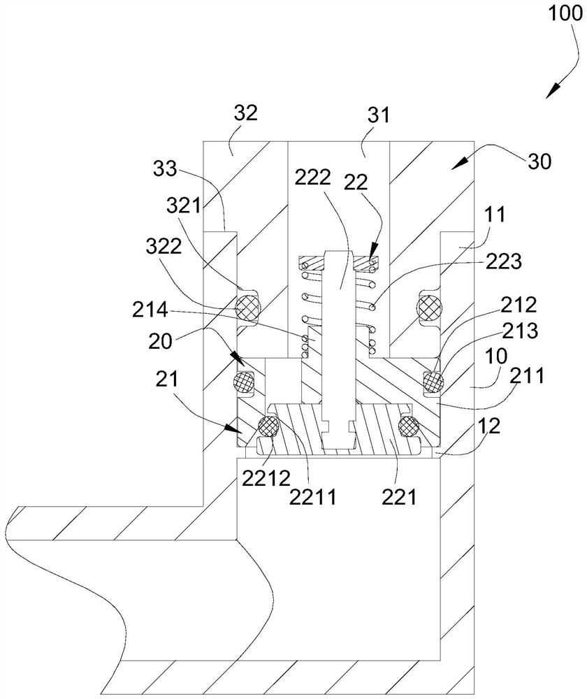
[0064] see figure 1 , one end of the installation body 211 abuts against the end of the sealing unit 30 away from the inlet, and the other end of the installation body 211 abuts against the resisting platform 12, so that no additional stoppers are required to fix the installation body 211, making the structure simple and stable, Space and cost are saved; at the same time, the valve body assembly 21 is firmly limited at a specified position through the limit on both sides of the installation body 211, preventing it from shifting and leaking, which affects the realization of device functions.

[0065] One end of the connection body 214 is connected to the installation body 211 , and the other end of the connection body 214 at least partially extends into the flow hole 31 , and both of them fix and limit the straight-through check valve 20 and the flow channel plate body 10 .

Embodiment 2

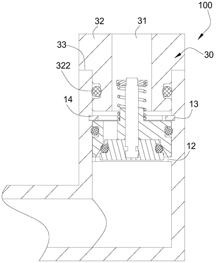
[0067] see figure 2 A groove 13 is formed on the inner wall of the flow channel plate body 10 in the circumferential direction, and the groove 13 is located between the sealing unit 30 and the mounting body 211 . The groove 13 is provided with a snap spring 14, and the snap spring 14 is sleeved outside the part of the connecting body 214. Through the circumferential clamping effect of the snap spring 14 on the mounting body 211, the position-limiting firmness of the mounting body 211 is further enhanced, thereby The overall structural stability of the valve body assembly 21 and even the straight-through check valve 20 is enhanced.

[0068] It can be understood that in other embodiments, other limiting parts can be provided between the runner plate body 10 and the installation body 211, as long as the installation body 211 and the runner plate body 10 can be fixed and limited. It is limited to the clip spring 14 described in this embodiment.

[0069] In this application, the...


PUM


Abstract

The invention relates to the technical field of runner plate structures, in particular to a runner plate structure. The runner plate structure is communicated with an external heat management component. According to the runner plate structure, a runner plate body comprises an inlet pipeline and is connected and communicated with an external heat management component through the inlet pipeline; the straight-through one-way valve is mounted in the inlet pipeline; the sealing unit is mounted at an inlet of the inlet pipeline and is in sealed connection with the runner plate body and the heat management component; wherein a circulation hole is formed in the sealing unit, a part of the straight-through one-way valve can be contained in the circulation hole, and the inlet pipeline is communicated with the heat management component through the circulation hole, so that a medium in the heat management component can flow into the inlet pipeline through the circulation hole and the straight-through one-way valve. The one-way valve has the advantages that the straight-through one-way valve and the sealing unit are integrated for use, and the sealing unit can accommodate part of the straight-through one-way valve, so that the structure is more compact, the occupied space in a pipeline is smaller, the weight is reduced, and the cost is reduced.

Description

technical field [0001] The invention relates to the technical field of flow channel plate structures, in particular to a flow channel plate structure. Background technique [0002] In order to save space and cost, the thermal management integrated module will be designed with a runner plate structure, and different thermal management components will be connected with the runner plate structure to form a thermal management integrated module with low cost, light weight, and small layout space. Thermal management components such as heat sinks, etc. In such a scheme arrangement, in order to realize switching of different modes, the flow channel plate structure needs to use various on-off valves, one-way valves, etc. to be installed in the flow channel plate body. [0003] Embedded one-way valves are usually used in the existing channel plate structure, so that the medium can only flow from the inlet pipe to the outlet pipe. The angle between the inlet axis and the outlet axis ...

Claims


Application Information

Patent Timeline
Patent Type & Authority Applications(China)
IPC IPC(8): F16K15/06F16K17/04F16K17/164F16K1/36F16K27/02
CPCF16K15/063F16K17/0413F16K17/164F16K1/36F16K27/0209
Inventor 鲍杰
Owner ZHEJIANG YINLUN MACHINERY
Why Eureka
Try Eureka