CAE automatic modeling method and system for kinematic pair, terminal and storage medium
A modeling method and kinematic pair technology, applied in constraint-based CAD, geometric CAD, design optimization/simulation, etc., can solve problems such as poor consistency of simulation results, modeling errors, and inconsistent methods, so as to shorten the development cycle, Improve work efficiency and improve modeling efficiency
- Summary
- Abstract
- Description
- Claims
- Application Information
AI Technical Summary
Problems solved by technology
Method used
Image
Examples
Embodiment 1
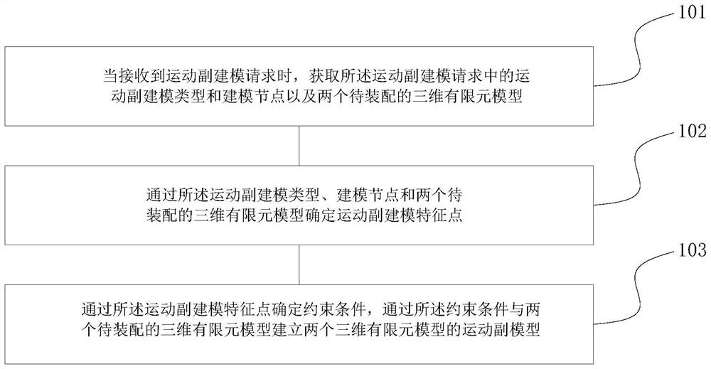
[0066] figure 1 It is a flow chart of a CAE automatic modeling method for a kinematic pair according to an exemplary embodiment, the method is used in a terminal, and the method includes the following steps:
[0067] Step 101. When a motion pair modeling request is received, obtain the motion pair modeling type and modeling nodes and two 3D finite element models to be assembled in the motion pair modeling request;
[0068] Step 102, determine the kinematic pair modeling feature points through the kinematic pair modeling type, modeling nodes and two 3D finite element models to be assembled;
[0069] Step 103 : Determine constraint conditions through the kinematic pair modeling feature points, and establish kinematic pair models of two 3D finite element models through the constraint conditions and the two 3D finite element models to be assembled.
[0070] Preferably, when the motion pair modeling request is received, the motion pair modeling type, modeling node and two 3D finit...
Embodiment 2
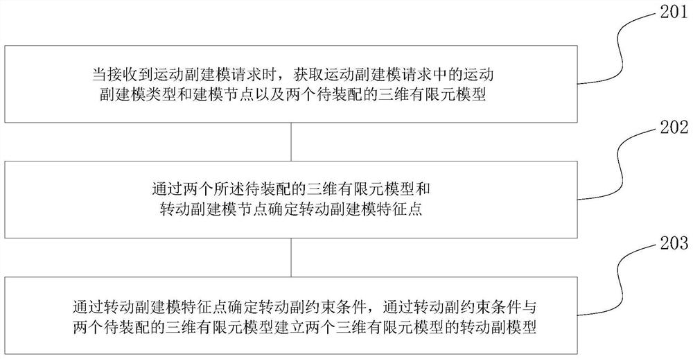
[0091] According to an exemplary embodiment, a CAE automatic modeling method of kinematic joints is shown. This method is used in a terminal. The method takes a rotating joint as an example, such as figure 2 As shown, the specific steps are as follows:
[0092] Step 201. When a motion pair modeling request is received, obtain the motion pair modeling type, modeling node and two 3D finite element models to be assembled in the motion pair modeling request, the specific contents include:
[0093] When a motion pair modeling request is received, start the motion pair modeling operation;
[0094] Obtain the kinematic joint modeling type corresponding to the kinematic joint modeling request as revolving joint and revolving joint modeling node;
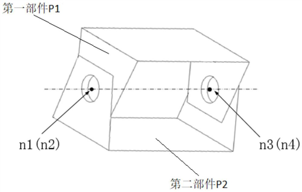
[0095] Obtain two three-dimensional finite element models to be assembled as the first part P1 and the second part P2 respectively, and determine two material types and database types through the first part P1 and the second part P2 respec...
Embodiment 3
[0108] According to an exemplary embodiment, a CAE automatic modeling method of a motion pair is shown, the method is used in a terminal, and the method takes a motion pair as an example, such as Figure 4As shown, since the number of constraints introduced by each rotating joint and moving joint is the same in the planar low-joint mechanism, the modeling method of the moving joint is the same as the modeling method of the moving joint except the kinematic joint modeling in the above steps The steps of the external modeling method with different feature point positions are the same, so they will not be repeated here.
PUM
 Abstract
Description
Claims
Application Information
 - R&D
- Intellectual Property
- Life Sciences
- Materials
- Tech Scout
- Unparalleled Data Quality
- Higher Quality Content
- 60% Fewer Hallucinations
Browse by: Latest US Patents, China's latest patents, Technical Efficacy Thesaurus, Application Domain, Technology Topic, Popular Technical Reports.
© 2025 PatSnap. All rights reserved.Legal|Privacy policy|Modern Slavery Act Transparency Statement|Sitemap|About US| Contact US: help@patsnap.com


