Clamp capable of being opened, closed and locked through guide block and intestinal canal implanting instrument
A technology of guide blocks and clamps, which is applied in the field of medical equipment, can solve the problems of unfavorable patient recovery, short intestinal indwelling time, and detachment, and achieve good structure maintenance, low structural complexity, and improved controllability.
- Summary
- Abstract
- Description
- Claims
- Application Information
AI Technical Summary
Problems solved by technology
Method used
Image

Examples
Embodiment 1
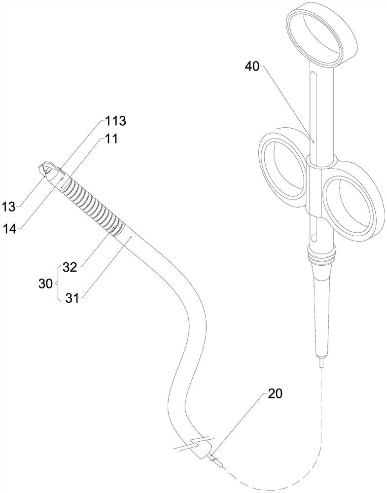
[0059] See details Figure 1 to Figure 6 As shown, the embodiment of the present invention provides a clamp that is opened and closed by the guide block 12, including a sleeve 11, a control line 20, an axial protection tube 30, a control mechanism 40, and two clamping legs 13, wherein:
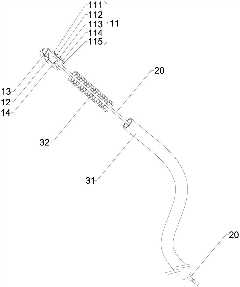
[0060] The distal end 111 of the sleeve is a tapered mouth shrinking toward the axis of the sleeve 11, the middle portion 113 of the sleeve is cylindrical and thin-walled, and the proximal end 114 of the sleeve is in the direction of the axis of the sleeve 11 relative to the middle portion 113 of the sleeve. Shrinking cylindrical thin-wall; two opening and closing grooves 112 are arranged symmetrically across the axis line of the sleeve 11 from the distal end 111 to the middle part 113 of the sleeve, surrounded by the distal end, middle part and proximal end (111, 113, 114) of the sleeve The inner space forms the inner space of the sleeve 11, and the sleeve top hole 115 of the proximal end 114...
Embodiment 2
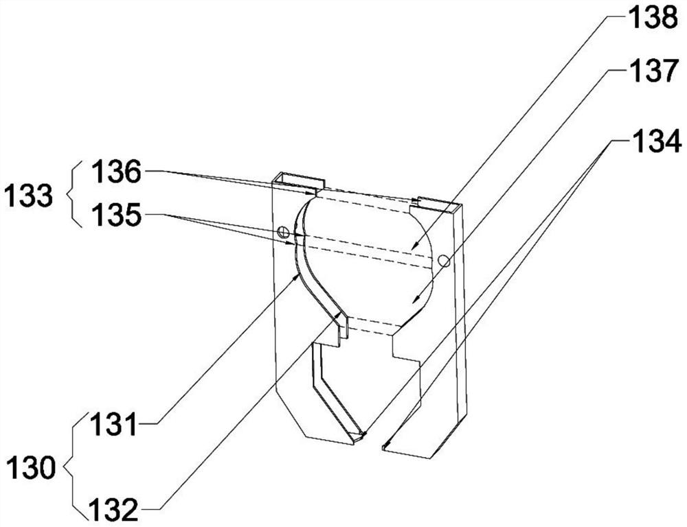
[0072] Such as Figure 7-9 As shown, on the basis of the solution in Embodiment 1, this embodiment improves the structure of the guide block 12 . Specifically, in this embodiment, the guide block 12 is set in the shape of a rounded rectangular block as a whole, and the two side surfaces of the guide block 12 paired with the two clip legs 13 are arranged on the grooves paired with the two clip legs 13, and as a pair with each The bottom wall 122 of the groove contacted by the guide surface 130 and each engaging surface 133 is an arc surface, and both contact surfaces are located on the same fitting spherical surface.
[0073] Due to the stamping and folding of the clip leg 13, the stability of the clip leg 13 structure is limited by the structural strength of the sheet thin-walled material itself. When the control mechanism 40 applies a traction force greater than the first preset force to the guide block 12 via the control line 20, the guide block 12 is pulled from the guide ...
Embodiment 3
[0077] Such as Figure 10 As shown, in order to further improve the structural stability of the clamp legs, in this embodiment, the structure of the clamp legs in Embodiment 1 is improved to form a clamp one. Specifically, the clamp leg 13' as a whole or the proximal part located in the sleeve 11 is improved to a solid structure, and the length outside the proximal part of the clamp is further extended to the proximal end; at the same time, the groove bottom wall 122 of the guide block 12 is modified to be The curved surface structure is not a spherical structure. Correspondingly, the proximal part of each guide surface 130 and each engaging surface 133 are set in a concave shape matched with the arc surface structure of the bottom wall 122 of the groove. The distal part 132 of each guide surface The configuration is in the shape of a slope tangent to the arc structure of the groove bottom wall 122 .
[0078] Through this setting, the structure of the proximal part of the cla...
PUM
 Abstract
Description
Claims
Application Information
 - R&D
- Intellectual Property
- Life Sciences
- Materials
- Tech Scout
- Unparalleled Data Quality
- Higher Quality Content
- 60% Fewer Hallucinations
Browse by: Latest US Patents, China's latest patents, Technical Efficacy Thesaurus, Application Domain, Technology Topic, Popular Technical Reports.
© 2025 PatSnap. All rights reserved.Legal|Privacy policy|Modern Slavery Act Transparency Statement|Sitemap|About US| Contact US: help@patsnap.com