Intelligent grinding and milling equipment combined with laser

A milling and intelligent technology, applied in the field of milling and milling, can solve the problems of inability to guarantee the stability of the workpiece, inconvenient movement and low degree of stability, and achieve the effect of improving stability, improving processing efficiency and ensuring comprehensiveness.

Pending Publication Date: 2022-04-22
陈卫
View PDF1 Cites 0 Cited by
  • Summary
  • Abstract
  • Description
  • Claims
  • Application Information

AI Technical Summary

Problems solved by technology

[0004] According to the above-mentioned patent, when the workpiece is clamped and used in this patent, the workpiece can be placed on the right clamping opening on the right fixture, and the right fixture clamps the rear end of the workpiece, so that the processing head can carry out the front end of the workpiece. Processing, after the front end of the workpiece is processed, under the drive of the left and right movement mechanism, the left and right fixtures move closer to each other, and the right fixture rotates around the axis of the front and back direction relative to the left and right movement mechanism so that the front end of the workpiece is aligned with the left fixture. Driven by the left and right movement mechanism, the workpiece enters the left clamping opening of the left clamp from the right clamping opening in the right clamping opening, the right clamping opening releases the workpiece, and the left clamping opening clamps the workpiece , so as to realize the reversing of the workpiece. However, this clamping method cannot guarantee the stability of the workpiece during processing. Although it replaces manual clamping, the degree of stability is not high. Iron filings falling on the left and right moving mechanism can easily cause inconvenient movement. Therefore, there is a need for a fixture that can not only maintain the stability of the workpiece clamping, but also prevent the iron filings from falling into it and can automatically switch the end of the workpiece.

Method used


Image

  • Intelligent grinding and milling equipment combined with laser
  • Intelligent grinding and milling equipment combined with laser
  • Intelligent grinding and milling equipment combined with laser

Examples


Embodiment Construction

[0042] In order to further understand the features, technical means, and specific objectives and functions achieved by the present invention, the present invention will be further described in detail below in conjunction with the accompanying drawings and specific embodiments.

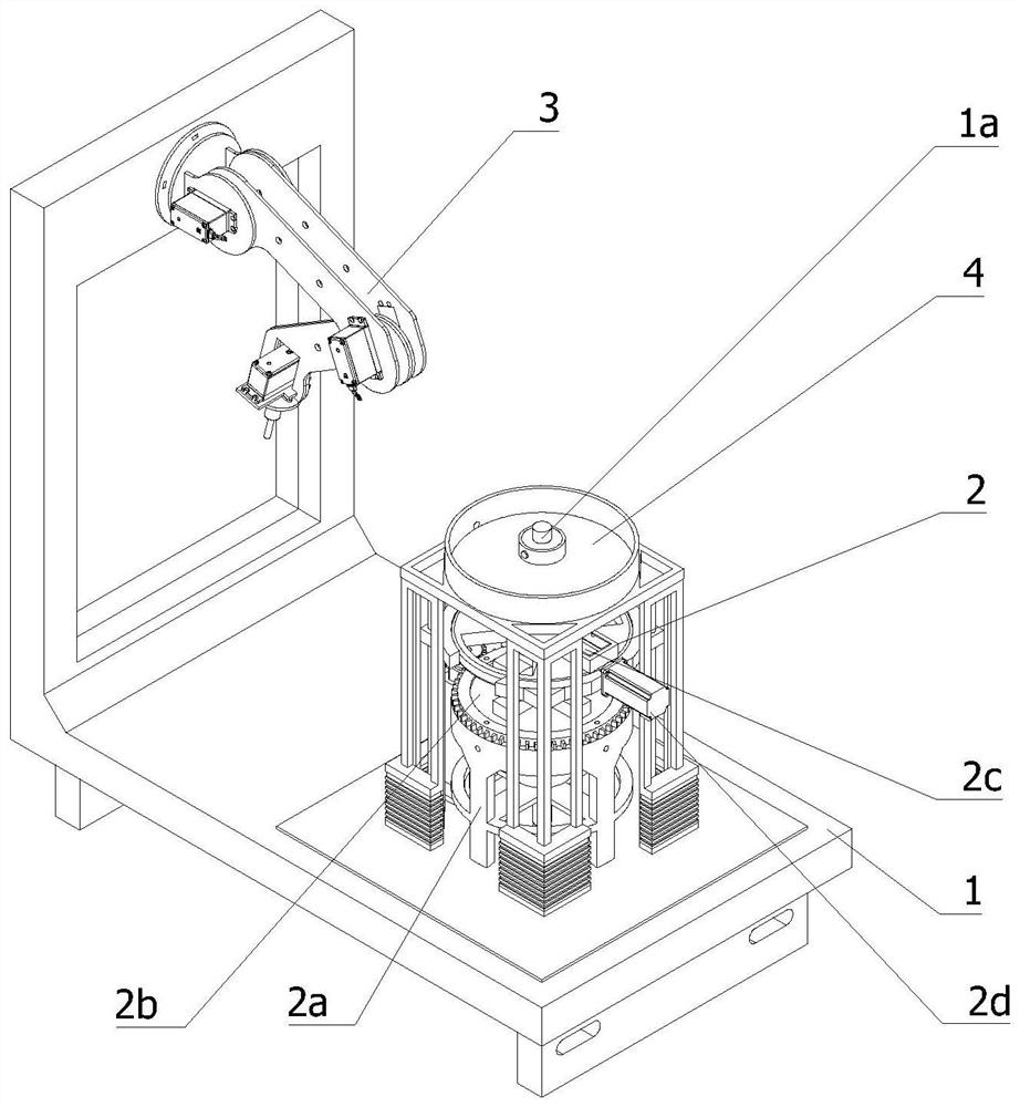
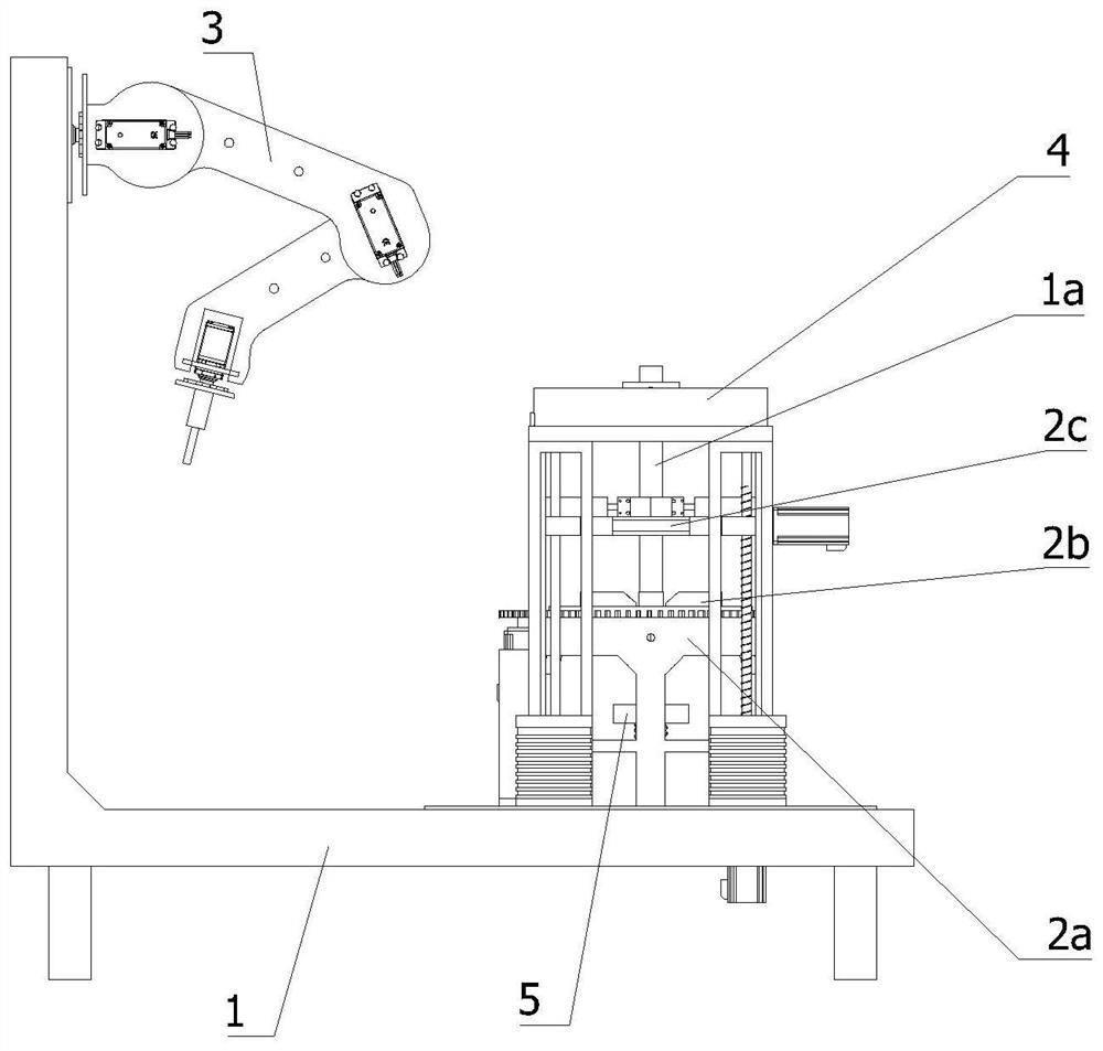
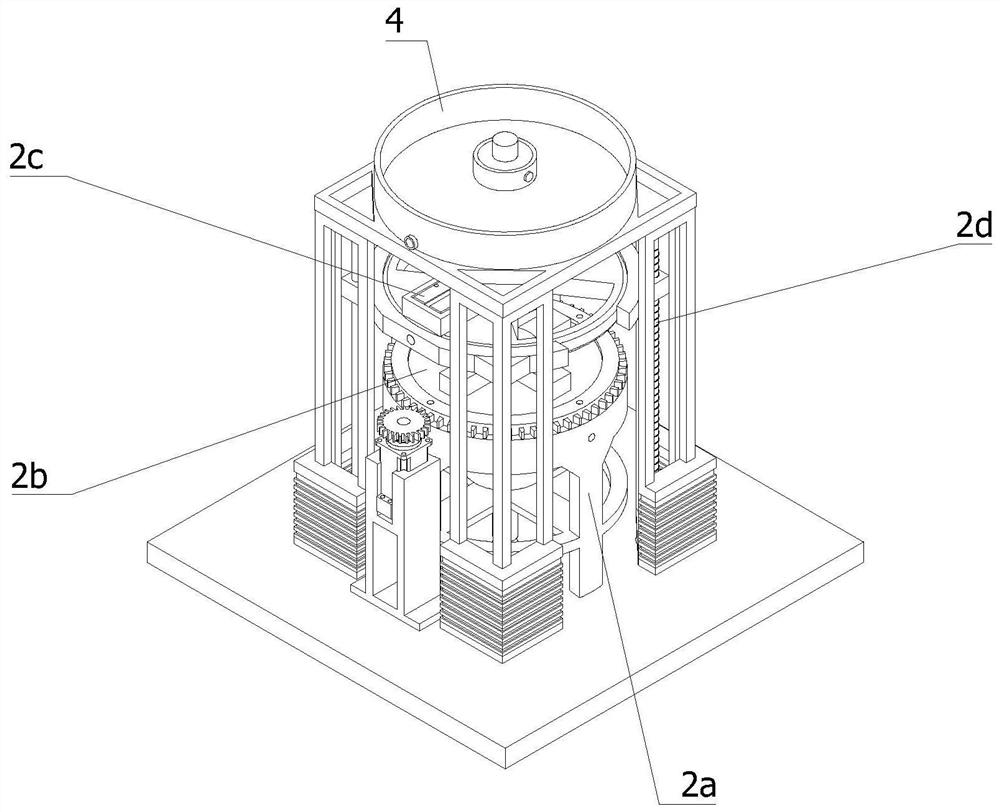
[0043] Such as Figure 1-Figure 6 As shown, this application provides:

[0044] An intelligent milling equipment combined with a laser, including a processing table 1 and a fixing device 2 arranged on the processing table 1 to fix the workpiece 1a, the workpiece 1a is in a rod-shaped structure, and the processing table 1 is also provided with a The laser milling robot 3 for processing, the fixing device 2 includes a support frame 2a and a first clamping mechanism 2b arranged on the support frame 2a to clamp the end of the workpiece 1a, and is arranged on the processing table 1 and is located in the first clamping mechanism 2b. There is a second clamping mechanism 2c above the clamping mechanism 2b for...


PUM


Abstract

The invention relates to the field of grinding and milling machining, in particular to laser-combined intelligent grinding and milling equipment which comprises a machining table and a fixing device arranged on the machining table, a workpiece is of a rod-shaped structure, a laser grinding and milling robot is further arranged on the machining table, and the fixing device comprises a supporting frame, a first clamping mechanism and a second clamping mechanism. The second clamping mechanism can drive the workpiece to move, a movable adjusting mechanism used for driving the second clamping mechanism to move is further arranged on the machining table, and a scrap iron treatment device used for cleaning waste is further arranged at the top end of the movable adjusting mechanism. Workpieces are operated through the first clamping mechanism, the second clamping mechanism and the movable adjusting mechanism, stability of the workpieces in the machining process is achieved, automatic conversion of the ends of the workpieces is achieved, the machining efficiency of the workpieces is improved, scrap iron is collected through the scrap iron treatment device, and the machining efficiency of the workpieces is improved. Scrap iron is prevented from falling into the first clamping mechanism and the second clamping mechanism to affect clamping of the workpiece.

Description

technical field [0001] The invention relates to the field of grinding and milling, in particular to an intelligent grinding and milling device combined with a laser. Background technique [0002] Traditional milling and grinding processing equipment can be used to process workpieces such as milling and grinding. At the same time, it can process various materials by combining laser grinding and milling. When laser processing is required for bars, for example, it is necessary to To process the bar stock into drill cutters, milling cutters, etc., it is necessary to process the two ends of the bar stock separately, so that one end of the bar stock is processed into a knife edge, and the other end is processed into a clamping part for installation. Most of the clamping devices process the other end after fixing one end, but if the other end of the bar needs to be processed, it needs to be re-clamped manually, which affects the efficiency of processing. [0003] The currently dis...

Claims


Application Information

Patent Timeline
IPC IPC(8): B23K26/36B23K26/08B23K26/16B23K26/70B23K37/04
CPCB23K26/36B23K26/702B23K37/04B23K26/16B23K26/0823
Inventor 陈伟
Owner 陈卫
Why Eureka
Try Eureka