
Machining process and machining device for double-end-face coated bearing

A processing technology, double-end face technology, applied in the direction of grinding workpiece support, grinding frame, grinding machine bed, etc., can solve the problems of machining surface error, large measurement accumulation error, difference not greater than 0.005mm, etc., to eliminate Positioning plane difference and machining plane error, meeting the requirements of parts matching, and the effect of scientific process methods

Active Publication Date: 2022-04-22
XIAN AERO ENGINE CONTROLS
View PDF26 Cites 0 Cited by
  • Summary
  • Abstract
  • Description
  • Claims
  • Application Information

AI Technical Summary

Problems solved by technology

However, the currently commonly used lubricant coating process cannot meet the requirements of design accuracy, and machining is required after coating. After machining, the thickness of the coating layer of the bearing and the flatness of the double end faces must be 0.003 mm, and the parallelism 0.005mm, the verticality of the inner hole is 0.005mm, while ensuring that the height difference with the matching bearing is not greater than 0.005mm
[0003] The double end faces of the bearings currently used (the general term for the rotating end face of the first bearing and the rotating end face of the second bearing) are all provided with a coating layer. During processing, the two coated surfaces need to be positioned as reference planes, but the two coated surfaces The difference in positioning flatness is large, resulting in errors in the processing surface and large accumulated measurement errors, which cannot meet the requirement that the height difference of the paired bearings is not greater than 0.005mm

Method used


Image

  • Machining process and machining device for double-end-face coated bearing
  • Machining process and machining device for double-end-face coated bearing
  • Machining process and machining device for double-end-face coated bearing

Examples


Embodiment 1

[0031] The processing technology of the double-end coated bearing of this embodiment includes the following steps:

[0032] 1) Fit the butt surface on the first bearing and the butt surface on the second bearing so that the first bearing and the second bearing are combined; use two clamping clips 1, and fit one of the clamping clips 1 Align and insert the positioning surface with the positioning groove on the first bearing, align and insert the positioning surface of the other clamping clip 1 with the positioning groove on the second bearing, so that the first bearing and the second bearing The relative position between them is fixed on the same reference plane, and the first coated surface of the first bearing and the first coated surface of the second bearing are ground using a grinding tool, so that the first coated surface of the first bearing and the second coated surface The first coated surface of the bearing is in the same plane;

[0033] 2) Turn the first bearing and...

Embodiment 2

[0041] The processing technology of the double-end coated bearing of this embodiment, on the basis of embodiment 1, it also includes the following steps:

[0042] 3) Measure the flatness, parallelism, and height difference of the double-end surfaces of the first bearing and the second bearing. After the measurement is completed, remove the first bearing and the second bearing from the reference plane; disassemble the first bearing The clamping clip 1 on the top and the clipping clip 1 on the second bearing complete the double-end coating of the first bearing and the second bearing.

Embodiment 3

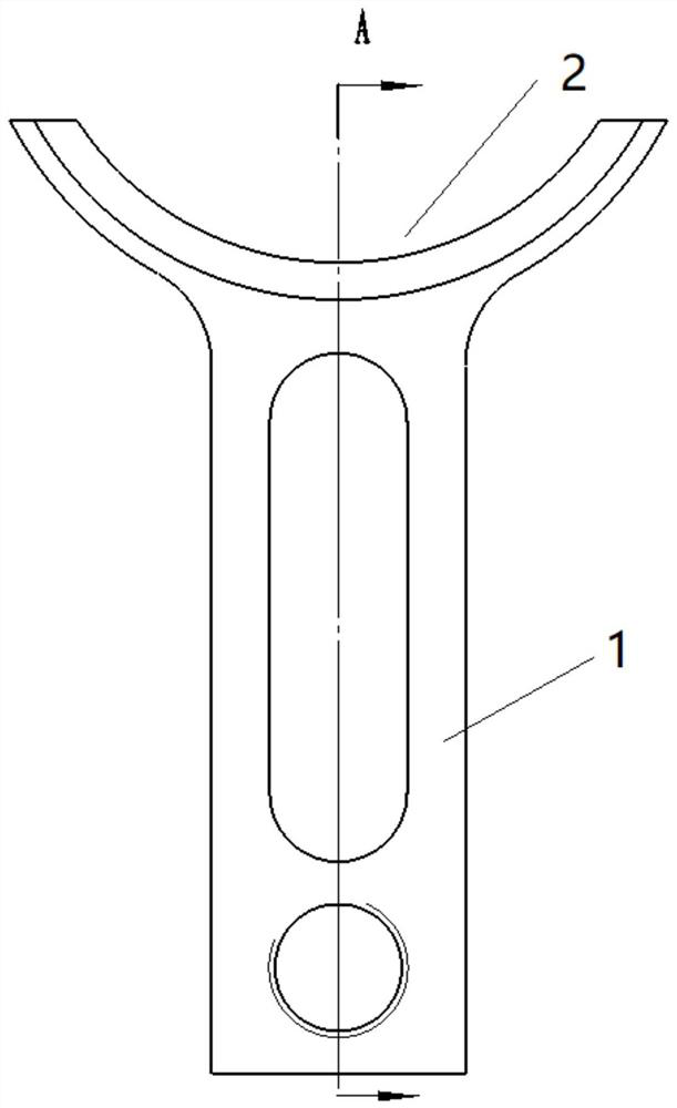
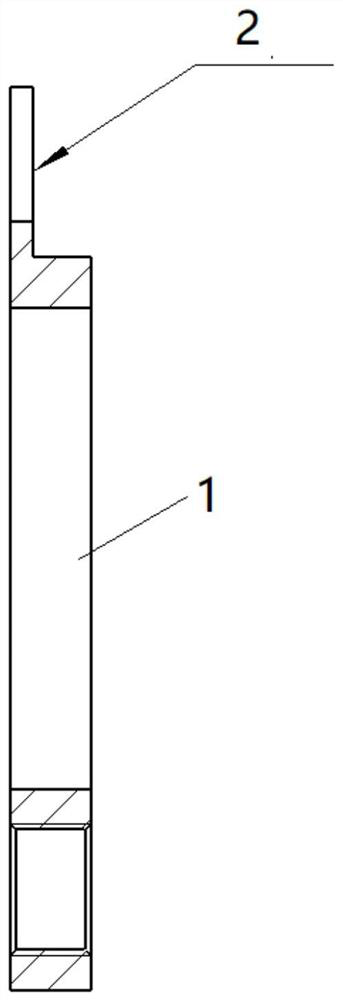
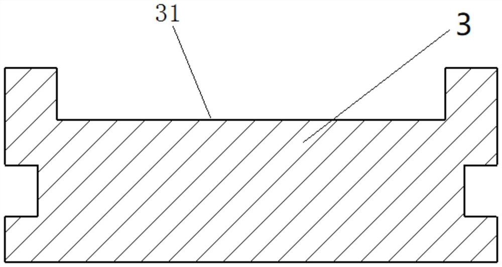
[0044] see Figure 1-Figure 3, the processing device of the double-end surface coated bearing in this embodiment, the processing device is formed based on the processing technology of embodiment 1 or embodiment 2, which includes clamping clip 1 and fixed base 3, clamping clip 1 includes a positioning part and a handle part, the handle part is a handle rod, the positioning part is an arc-shaped structure, and a positioning surface 2 is arranged on the inner side of the arc-shaped structure, and the positioning surface 2 is an L-shaped structure in cross section, and the positioning surface The shape of 2 coincides with the shape of the positioning groove on the first bearing / second bearing, and the handle part is fixedly connected to the outside of the arc-shaped structure and arranged along the radial direction of the arc-shaped structure.

[0045] The top of the fixed base 3 is provided with a reference groove, and the bottom wall of the reference groove is a positioning refe...


PUM


Abstract

The invention provides a machining process and a machining device for double-end-face coated bearings, and belongs to the technical field of machining, the machining process comprises the following steps: 1) splicing a first bearing and a second bearing, simultaneously clamping and fixing the first bearing and the second bearing at the same reference height, grinding a first coated surface of the first bearing and a first coated surface of the second bearing, and grinding the first coated surface of the first bearing and the second coated surface of the second bearing; the first coating surface of the first bearing and the first coating surface of the second bearing are positioned on the same plane; and (2) the first bearing and the second bearing are turned over, the first coating face of the first bearing and the first coating face of the second bearing are located on the same datum plane, and the second coating face of the first bearing and the second coating face of the second bearing are ground so that the second coating face of the first bearing and the second coating face of the second bearing can be located on the same plane.

Description

technical field [0001] The invention belongs to the technical field of mechanical processing, and relates to the processing technology of high-precision bearings, in particular to the processing technology and processing device of double-end coated bearings. Background technique [0002] High-precision bearings are precision parts commonly used in aviation products. During the bearing processing process, it is necessary to coat the rotating end surface of the bearing with lubricant to improve the wear resistance, fatigue resistance and product life of the bearing. However, the currently commonly used lubricant coating process cannot meet the requirements of design accuracy, and machining is required after coating. After machining, the thickness of the coating layer of the bearing and the flatness of the double end faces must be 0.003 mm, and the parallelism 0.005mm, the verticality of the inner hole is 0.005mm, and at the same time ensure that the height difference with the ...

Claims


Application Information

Patent Timeline
Patent Type & Authority Applications(China)
IPC IPC(8): B24B1/00B24B41/06B24B41/02
CPCB24B1/00B24B41/06B24B41/02
Inventor 任燕飞张晓辉王彦雷刚曾建勇张军飞李燕张宏刚
Owner XIAN AERO ENGINE CONTROLS
Learn More