Electro-optic intensity modulator frequency response testing device and method

A technology of electro-optical intensity modulation and frequency response testing, which is applied to electromagnetic transmitters, electrical components, electromagnetic wave transmission systems, etc., can solve the problems of lack of modulation coefficient of electro-optical intensity modulator and half-wave voltage test method, etc., and achieve self-calibration measurement , avoid uneven response, and reduce the effect of bandwidth requirements

Pending Publication Date: 2022-04-22
UNIV OF ELECTRONIC SCI & TECH OF CHINA
View PDF0 Cites 0 Cited by
  • Summary
  • Abstract
  • Description
  • Claims
  • Application Information

AI Technical Summary

Problems solved by technology

[0004] At present, there are many methods for measuring the frequency response of electro-optic intensity modulators, but there is still a lack of fast, high-precision, high-resolution electro-optic intensity modulator modulation coefficient and half-wave voltage test methods through single-tone driving

Method used


Image

  • Electro-optic intensity modulator frequency response testing device and method
  • Electro-optic intensity modulator frequency response testing device and method
  • Electro-optic intensity modulator frequency response testing device and method

Examples


Embodiment

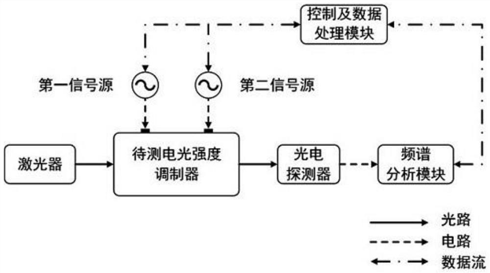
[0046] The block diagram of the testing device of the present invention is as figure 1 shown. The frequency of the laser output optical carrier is f 0 =193.1THz, the optical carrier is sent to the electro-optical intensity modulator to be tested for modulation, and the output frequency f of the first signal source is set 1 =10GHz, loaded on the RF electrode of the electro-optical intensity modulator to be tested; the second signal source output frequency f b =100kHz is loaded on the bias electrode of the electro-optical intensity modulator to be tested, and the modulated optical signal output by the electro-optic intensity modulator to be tested is sent to the photodetector for photoelectric conversion, and the beat frequency signal is generated and sent to the spectrum analysis module for analysis and recording .

[0047] When the output signal of the first signal source is in the off state, the low-frequency signal component extracted by the spectrum analysis module is 10...


PUM


Abstract

The invention discloses an electro-optic intensity modulator frequency response testing device and method, a laser is utilized to emit a beam of optical carrier wave, the optical carrier wave is sent to a to-be-tested electro-optic intensity modulator, a radio frequency driving electrode of the to-be-tested electro-optic intensity modulator is connected with a first signal source, a bias electrode is connected with a second signal source, the first signal source outputs a sinusoidal signal with the frequency f1, and the second signal source outputs a sinusoidal signal with the frequency f2; the second signal source outputs sinusoidal signals with the frequency of fb, optical carriers are modulated, and optical modulation signals output by the electro-optical intensity modulator to be detected enter a photoelectric detector for frequency beating; the output power of the first signal source is controlled, the signal amplitude with the frequency being fb in the beat frequency signal and the output power of the first signal source are extracted through a spectrum analysis module, and the modulation coefficient and the half-wave voltage of the electro-optic intensity modulator to be measured at the frequency f1 are obtained through calculation and fitting analysis of extracted data; the first signal source is controlled to scan under different driving powers, and the frequency response of the electro-optical intensity modulator to be measured can be obtained by repeating the operation.

Description

technical field [0001] The invention belongs to the field of optoelectronic devices, in particular to the field of frequency response testing of optoelectronic devices, in particular to an electro-optical intensity modulator frequency response testing device and method. Background technique [0002] Electro-optical intensity modulator is a key device responsible for electro-optical conversion in optical communication systems and microwave photonic links, and its frequency response parameters (such as modulation efficiency, half-wave voltage, etc.) greatly affect the performance of the entire system or link. . Accurate measurement of the modulation coefficient and half-wave voltage of electro-optical intensity modulators is crucial for the device performance evaluation of electro-optical intensity modulators and high-frequency applications in optical communication and microwave photonic systems. [0003] The existing test methods for measuring the frequency response of elect...

Claims


Application Information

Patent Timeline
IPC IPC(8): H04B10/079H04B10/54
CPCH04B10/0795H04B10/54
Inventor 张尚剑徐映王梦珂何禹彤顾超宇刘永
Owner UNIV OF ELECTRONIC SCI & TECH OF CHINA
Why Eureka
Try Eureka