Rotary tillage seeder

The technology of a seeder and a rotary tiller is applied in the field of agricultural machinery, which can solve the problems of poor ventilation and light transmission of wheat plants, inability to put fertilizers evenly, and unfavorable fertilizer storage in the fields, so as to ensure ventilation and light transmission, good ventilation and light transmission, fertilizer layer constant effect

Pending Publication Date: 2022-04-26
JIANGSU PROVINCIAL AGRI RECLAMATION & DEV CO LTD
View PDF0 Cites 1 Cited by
  • Summary
  • Abstract
  • Description
  • Claims
  • Application Information

AI Technical Summary

Problems solved by technology

[0002] Although the current wheat compound operation machine has functions such as ditching, leveling, sowing, and suppression, the operation effect is equal row spacing, which makes the wheat plants poorly ventilated and light-transmitting, which affects the wheat yield; and the fields between the rows where no wheat is planted are also plowed. , which consumes more operating power, and is not conducive to field fertilizer storage; at the same time, this kind of operating machine also needs to cooperate with a fertilizer spreader or artificial fertilizer, and manual fertilizer needs to cooperate with the mechanical soil preparation process to implement it well
Therefore, this kind of operation method of sowing and fertilizing separately prevents the fertilizer from being accurately and evenly distributed in the sowing area, causing serious waste and loss, and the fertilizer layer is chaotic and the amount of fertilizer at the bottom is small.

Method used


Image

  • Rotary tillage seeder
  • Rotary tillage seeder
  • Rotary tillage seeder

Examples


Embodiment Construction

[0026] The accompanying drawings in the embodiments of the present invention will clearly and completely describe the technical solutions in the embodiments of the present invention below.

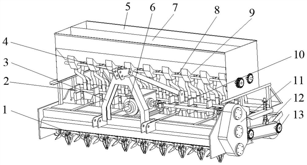
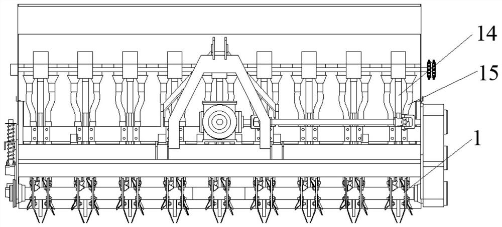
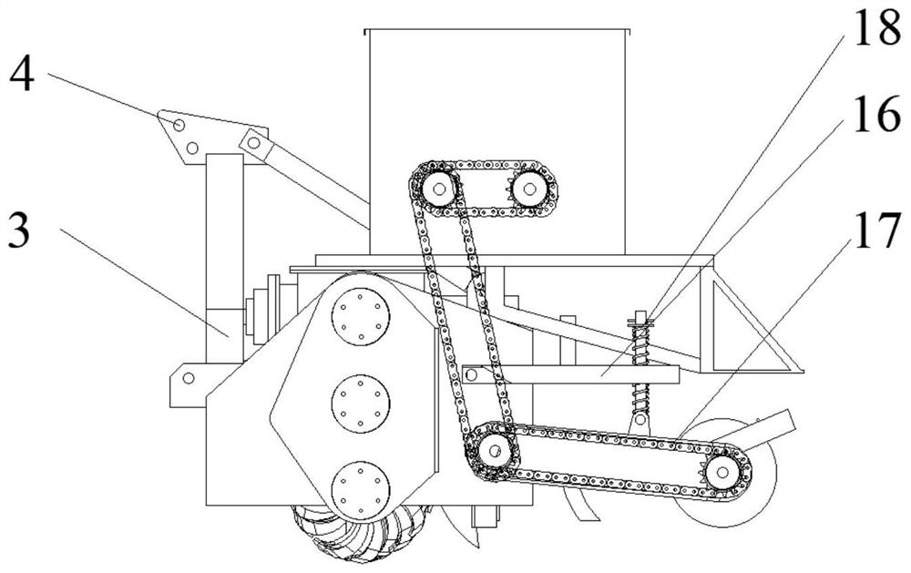
[0027] like figure 1 , figure 2 , image 3 as well as Figure 4 , the wide and narrow row protective tillage planter with side deep fertilization of the present embodiment mainly consists of a walking frame, a rotary blade shaft 1-1 and a pressing wheel 12 that are rotatably supported on the walking frame, and are connected to the rotary blade shaft 1-1. The rotary tiller 1-2 on the top and the transmission device fixed on the walking support, the seeding box 5, the fertilization box 7, the core share 2-3, and some rotary tiller 1-2 are arranged in pairs by the same group spacing. On the rotary blade shaft 1, the two rotary blades 1-2 in each group of blades are arranged symmetrically with the same blade spacing, and the group spacing is greater than the blade spacing, forming alternat...


PUM


Abstract

The rotary tillage seeder comprises a walking support, a rotary tillage cutter shaft, a press wheel, rotary tillage cutters, a seeding box, a fertilization box, a transmission device and a core ploughshare, the multiple rotary tillage cutters are arranged on the rotary tillage cutter shaft in pairs, and the two rotary tillage cutters in each group are symmetrically arranged; the plurality of core ploughshares and the plurality of fertilizer discharging pipes on the fertilizer applying box are respectively arranged along the axial direction parallel to the rotary tillage cutter shaft, and are positioned at the central symmetry positions corresponding to the rotary tillage cutter group; a plurality of seed-metering pipes on the seeding box are arranged in pairs and are arranged at equal intervals in a manner that the central symmetry positions of the seed-metering pipes are consistent with the central symmetry positions of the rotary blade groups. The row-to-row rotary tillage device has the advantages that the rotary tillage blades of the row-to-row rotary tillage device are only arranged at the narrow-distance positions of the adjacent seed-metering pipes of the seeder, power consumption is reduced, soil corresponding to the wide-distance positions of the adjacent seed-metering pipes of the seeder is not subjected to rotary tillage during operation of the seeder, and the purpose of protective tillage can be achieved; wide-narrow row alternation and plant position staggering of wheat seedlings are formed after sowing, and ventilation and light transmission of wheat are facilitated.

Description

technical field [0001] The invention relates to the technical field of agricultural machinery, in particular to a wide and narrow row rotary tillage seeder with side deep fertilization. Background technique [0002] Although the current wheat compound operation machine has functions such as ditching, leveling, sowing, and suppression, the operation effect is equal row spacing, which makes the wheat plants poorly ventilated and light-transmitting, which affects the wheat yield; and the fields between the rows where no wheat is planted are also plowed. , which consumes more work power, and is not conducive to field fertilizer storage; at the same time, this kind of operating machine must cooperate with a fertilizer spreader or artificial fertilizer, and manual fertilizer needs to cooperate with the mechanical soil preparation process to implement it well. Therefore, this operation method of separating seeding and fertilization makes it impossible for the fertilizer to be accur...

Claims


Application Information

Patent Timeline
Patent Type & Authority Applications(China)
IPC IPC(8): A01B49/06A01B33/02A01B33/12A01C7/06A01C5/06
CPCA01B49/065A01B33/021A01B33/12A01C7/06A01C5/062A01C5/068A01C5/066
Inventor 邢全道朱松叶凌凤田祥瑞刘刚李玲仇维佑何彦平
Owner JIANGSU PROVINCIAL AGRI RECLAMATION & DEV CO LTD
Why Eureka
Try Eureka