Eureka AIR delivers breakthrough ideas for toughest innovation challenges, trusted by R&D personnel around the world.

Soldering machine for connecting data line and transmission head

A soldering machine and data line technology, which is applied in the field of soldering machines, can solve problems such as unfavorable production, prolonged welding time, and increased nitrogen consumption

Inactive Publication Date: 2022-04-26
深圳市东盛伟业电子有限公司
View PDF0 Cites 0 Cited by
  • Summary
  • Abstract
  • Description
  • Claims
  • Application Information

AI Technical Summary

Problems solved by technology

[0003] There are still some shortcomings in the existing soldering machine. When the existing soldering machine melts the solder, the soldering iron tip is used to contact and melt the solder when it is close to the place to be welded, which will result in prolonged welding time. It is beneficial to modern industrial production, and the action of on-site melting will cause part of the solder to follow the melted solder to the place to be welded when it is not melted, resulting in a large amount of impurities in the finished soldering product, and nitrogen will be ejected from the side of the soldering iron tip, which will make it still Unsolidified solder has the problem of solder liquid displacement, and in order to ensure an oxygen-free environment at the place to be soldered, it is necessary to keep nitrogen spraying continuously, which leads to increased nitrogen consumption and higher costs

Method used


Image

  • Soldering machine for connecting data line and transmission head
  • Soldering machine for connecting data line and transmission head
  • Soldering machine for connecting data line and transmission head

Examples


Embodiment Construction

[0026] The following will clearly and completely describe the technical solutions in the embodiments of the present invention with reference to the accompanying drawings in the embodiments of the present invention. Obviously, the described embodiments are only some, not all, embodiments of the present invention. Based on the embodiments of the present invention, all other embodiments obtained by persons of ordinary skill in the art without making creative efforts belong to the protection scope of the present invention.

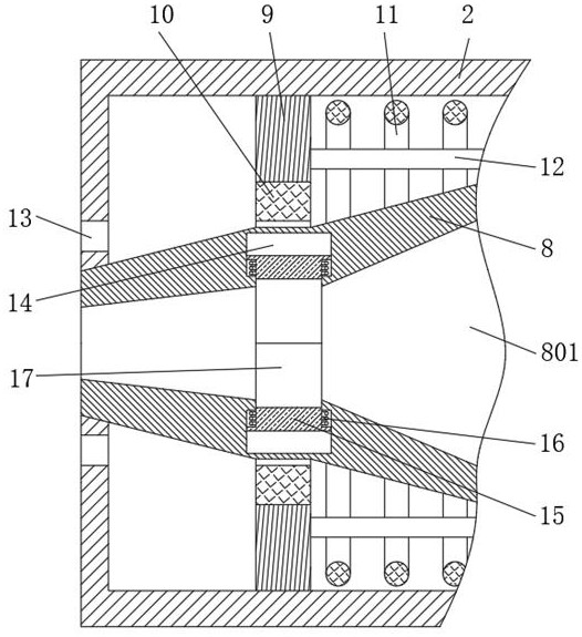
[0027] see Figure 1-Figure 5 , a soldering machine for connecting a data line to a transmission head, including a fixed seat 1, which is fixedly connected to the moving parts of the soldering machine, so that the soldering machine can move the device to the place to be welded through the fixed seat 1 , the fixed seat 1 is fixedly sleeved with circuit wires, one end of the fixed seat 1 is fixedly connected with the external cylinder 2 and the heating pipe 3, a...


PUM


Abstract

The invention relates to the technical field of welding, and discloses a tin soldering machine for connecting a data line and a transmission head, the tin soldering machine comprises a fixed seat, one end of the fixed seat is fixedly connected with an outer cylinder and a heating pipe, and the middle part of one end, far away from the fixed seat, of the outer cylinder is provided with air outlets which are annularly and uniformly distributed; a blocking piston is movably connected to the same side of an inner cavity of the outer cylinder in a sleeved mode, an annular magnet I is fixedly connected to the inner side of the blocking piston, a heating cavity is formed in the heating pipe, and an electric heating wire is wound in the heating cavity. Through the designed heating pipe, the electric soldering iron and the tin feeding pipe, tin alloy solder can directly enter the melting cavity of the electric soldering iron through the tin feeding pipe, the solder is molten in the melting cavity in advance, a welding solution can be directly sprayed out to a to-be-welded position during welding, and the problems that the welding time is long due to the fact that the solder is molten again during welding, and the welding quality is poor are solved. The melting effect is not ideal when the welding flux is contacted with the electric soldering iron; the welding part has more impurities; and the quality is poor.

Description

technical field [0001] The invention relates to the field of welding technology, in particular to a soldering machine for connecting a data line to a transmission head. Background technique [0002] The soldering machine is a kind of automatic soldering equipment, which mainly controls the movement of the soldering iron head assembly to the place to be welded through the control program, so that the outer side of the high-temperature soldering iron head is in contact with the soldering alloy solder delivered by the tin breaking machine, so that the high-temperature soldering iron head The soldering iron tip melts the solder in a short period of time, and solders the place to be welded. At the same time, the outer side of the soldering iron tip will spray nitrogen gas from the jet tube to protect the soldering place to avoid the oxidation reaction of the solder. [0003] There are still some shortcomings in the existing soldering machine. When the existing soldering machine m...

Claims


Application Information

Patent Timeline
Patent Type & Authority Applications(China)
IPC IPC(8): B23K3/06B23K3/08
CPCB23K3/0615B23K3/08
Inventor 杨栋材黄焕敏
Owner 深圳市东盛伟业电子有限公司
Why Eureka
Eureka Blog
Learn More