
Polishing device and method for communication shell machining

A technology for polishing devices and shells, which is applied in the direction of grinding drive devices, metal processing equipment, grinding/polishing equipment, etc. It can solve the problems of low grinding efficiency, many surface burrs, easy to damage gloves, etc., and achieve the effect of improving work efficiency

Pending Publication Date: 2022-04-26
芜湖仅一轻量化科技有限公司
View PDF10 Cites 1 Cited by
  • Summary
  • Abstract
  • Description
  • Claims
  • Application Information

AI Technical Summary

Problems solved by technology

[0002] Wireless communication uses radio waves instead of cables to achieve communication between devices. This communication method has the advantages of fast and simple installation and maintenance, not affected by the site terrain environment, and low cost. The rich products can meet the needs of users in terms of communication distance and communication. Due to the different requirements on the speed, the plate is bent during the processing of the communication case, and then the cover is processed. The movable door of the traditional communication case has many burrs on the surface, and it is easy to damage the gloves when disassembling and assembling, and even cause hand Therefore, it is generally necessary to grind and polish the surface of the communication shell. This polishing treatment also helps to improve the smoothness of the shell surface and contributes to the coating of the protective layer. The existing grinding and polishing devices require continuous manual work. Feeding and polishing are less efficient. Based on this, a polishing and polishing device and method for automatic feeding are now provided.

Method used


Image

  • Polishing device and method for communication shell machining
  • Polishing device and method for communication shell machining
  • Polishing device and method for communication shell machining

Examples


Embodiment 1

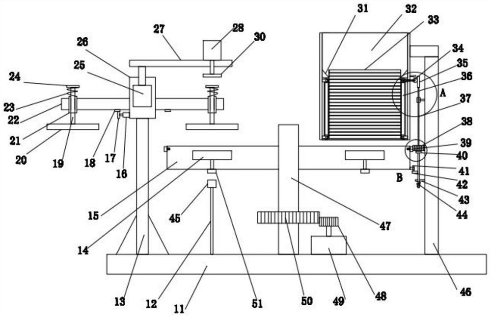
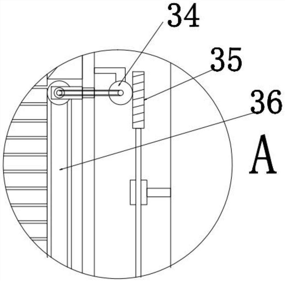
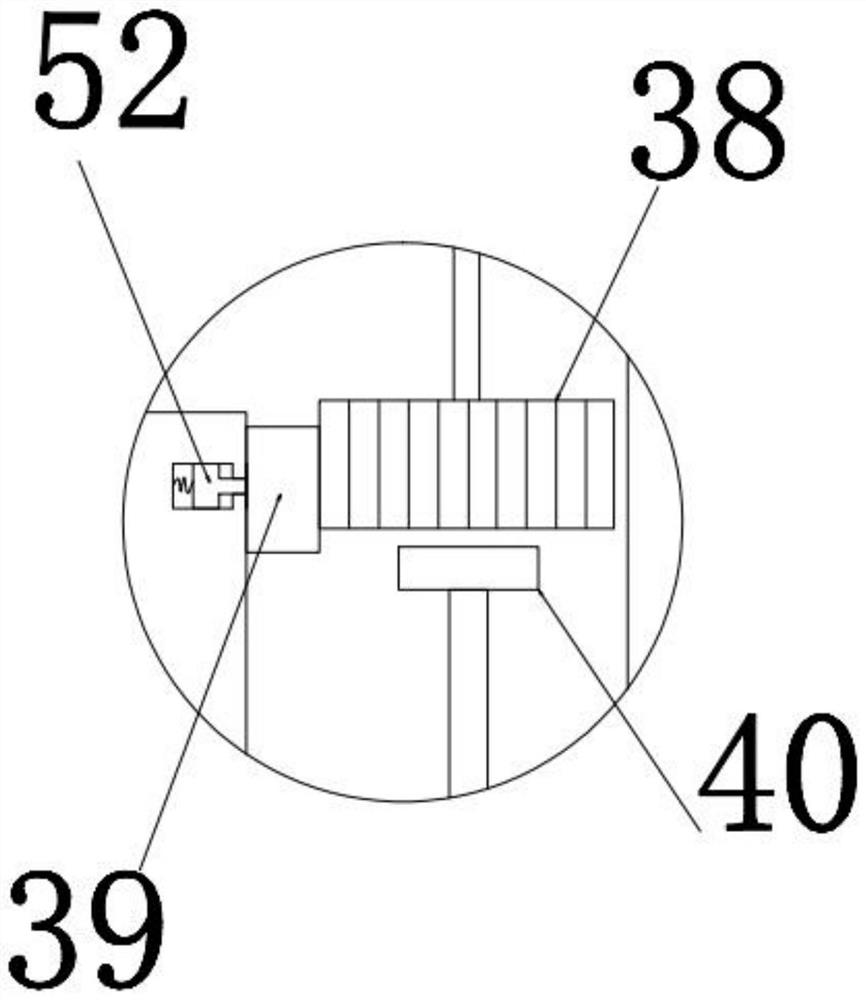
[0024] see Figure 1-Figure 5 , in an embodiment of the present invention, a polishing device for communication shell processing includes a base 11 and a rotating column 47 that is rotated at the middle position of its upper end, and the lower end of the rotating column 47 is connected to drive it to rotate to realize station switching The rotating drive member, the upper end of the rotating column 47 is coaxially provided with a rotating disk 15 for placing workpieces, and the inner array of the rotating disk 15 is distributed with several magnetic adsorbers 14 for auxiliary positioning of the workpieces. The bottom of the magnetic absorber 14 is provided with a signal receiver 51 for starting it, the upper end of the base 11 is provided with a fixed rod 12, and the end of the fixed rod 12 is provided with a signal transmitter for sending an opening signal to the signal receiver 51 45, only when the rotating disk 15 drives the magnetic force absorber 14 to rotate to the posit...


PUM


Abstract

The polishing device comprises a base and a rotating column rotationally arranged in the middle of the upper end of the base, the lower end of the rotating column is connected with a rotating driving part used for driving the rotating column to rotate so as to achieve station switching, and a rotating disc used for containing workpieces is coaxially arranged at the upper end of the rotating column; a plurality of magnetic adsorbers used for conducting auxiliary positioning on workpieces are distributed in the rotating disc in an array mode, signal receivers used for starting the magnetic adsorbers are arranged at the bottoms of the magnetic adsorbers, and a fixing rod is arranged at the upper end of the base. And one-by-one feeding by operators is not needed, automatic feeding can be carried out, fixing is carried out in cooperation with an electromagnetic adsorption positioning mode, and the working efficiency is effectively improved.

Description

technical field [0001] The invention relates to the technical field of polishing equipment, in particular to a polishing device and method for processing communication shells. Background technique [0002] Wireless communication uses radio waves instead of cables to achieve communication between devices. This communication method has the advantages of fast and simple installation and maintenance, not affected by the site terrain environment, and low cost. The rich products can meet the needs of users in terms of communication distance and communication. Due to the different requirements on the speed, the plate is bent during the processing of the communication case, and then the cover is processed. The movable door of the traditional communication case has many burrs on the surface, and it is easy to damage the gloves when disassembling and assembling, and even cause hand Therefore, it is generally necessary to grind and polish the surface of the communication shell. This po...

Claims


Application Information

Patent Timeline
IPC IPC(8): B24B29/02B24B27/00B24B41/00B24B41/02B24B41/06B24B47/12B24B47/00B24B41/04B24B1/00
CPCB24B29/02B24B27/0076B24B41/005B24B41/02B24B41/06B24B47/12B24B47/00B24B41/04B24B1/00
Inventor 刘飞史沸涛朱志强
Owner 芜湖仅一轻量化科技有限公司
Learn More