
Rope-driven high-precision two-degree-of-freedom parallel robot

A rope-driven, degree-of-freedom technology, applied in the field of robotics, can solve problems that affect the positioning accuracy of the moving platform at the end of the robot, reduce the service life of the rope, and friction and wear energy, etc., to achieve avoiding redundant drives, extending service life, and high dynamic movement Effect

Active Publication Date: 2022-04-26
TSINGHUA UNIV
View PDF6 Cites 0 Cited by
  • Summary
  • Abstract
  • Description
  • Claims
  • Application Information

AI Technical Summary

Problems solved by technology

In the traditional cable-driven parallel robot, with the movement of the terminal moving platform, the cable exit point on the drum is constantly changing, and the cable exit point on the pulley is also constantly changing. However, in the kinematic model of the cable-driven robot In the above, the cable exit point on the drum and the cable exit point on the pulley will be idealized as a fixed point, so as the terminal moving platform moves, the ideal cable exit point in the kinematics model of the cable drive robot There will be a deviation between the position of the point position and the actual position of the cable exit point, which will cause a large deviation between the robot control model and the actual situation of the traditional cable-driven parallel robot, which will affect the positioning accuracy of the moving platform at the end of the robot
Therefore, accuracy becomes the main obstacle limiting the application of cable parallel robots
In addition, the rope is guided through multiple pulleys, causing frictional wear and energy loss in the process, reducing rope life

Method used


Image

  • Rope-driven high-precision two-degree-of-freedom parallel robot
  • Rope-driven high-precision two-degree-of-freedom parallel robot
  • Rope-driven high-precision two-degree-of-freedom parallel robot

Examples


Embodiment Construction

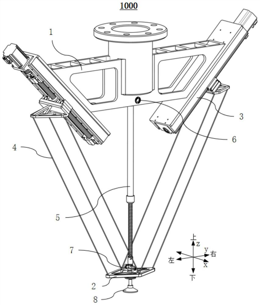
[0049] Embodiments of the present invention are described in detail below, examples of which are shown in the drawings, wherein the same or similar reference numerals designate the same or similar elements or elements having the same or similar functions throughout. The embodiments described below by referring to the figures are exemplary only for explaining the present invention and should not be construed as limiting the present invention.

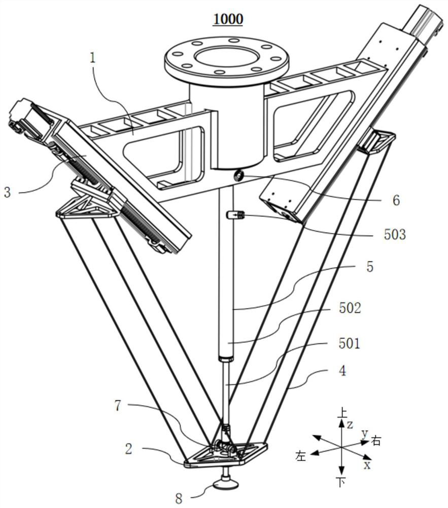
[0050] Combine below Figure 1 to Figure 10 A high-precision two-degree-of-freedom parallel robot 1000 driven by a cable according to an embodiment of the present invention will be described.

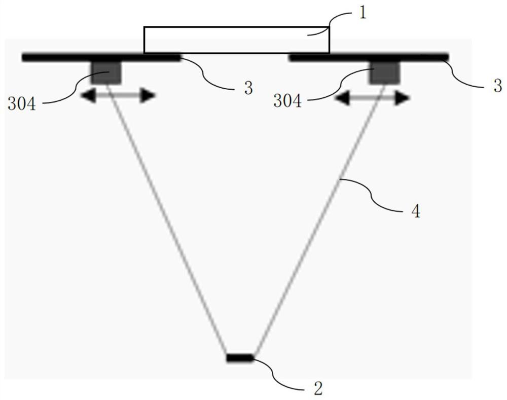
[0051] Such as Figure 1 to Figure 4 As shown, the cable-driven high-precision two-degree-of-freedom parallel robot 1000 according to the embodiment of the present invention includes a frame 1 , a moving platform 2 , two sets of driving assemblies 3 , two sets of parallel cable systems 4 and auxiliary tensioning assemblies 5 . Among them, the mo...


PUM


Abstract

The invention discloses a high-precision two-degree-of-freedom parallel robot driven by ropes. The high-precision two-degree-of-freedom parallel robot comprises a rack, a movable platform, two driving assemblies, two parallel rope systems and an auxiliary tensioning assembly. Wherein the movable platform and the rack are oppositely arranged at an interval; the two driving assemblies are ball screw pair driving assemblies and are arranged on the left side and the right side of the rack in a bilateral symmetry mode. The two groups of parallel cable systems are arranged in bilateral symmetry and are positioned in the same mounting plane with the two groups of driving assemblies; one ends of the two parallel cable systems are connected to the two driving assemblies in a one-to-one correspondence mode, and the other ends of the two parallel cable systems are connected to the movable platform. The number of ropes of each group of parallel cable system is not less than three, and the lengths are all equal; the two ends of the auxiliary tensioning assembly are connected to the center of the rack and the center of the movable platform correspondingly and used for tensioning all the ropes in each parallel cable system all the time. According to the robot, positioning of the movable platform is more accurate, the parallel cable system is free of friction loss, and redundant driving is avoided.

Description

technical field [0001] The invention relates to the technical field of robots, in particular to a high-precision two-degree-of-freedom parallel robot driven by cables. Background technique [0002] The cable-driven parallel robot is a special type of parallel robot, which uses lightweight and flexible cables instead of rigid rods as the kinematic chain to realize the motion drive of the terminal moving platform. The cable-driven parallel robot inherits the high-load configuration advantages of the rigid parallel mechanism, and at the same time has the characteristics of small moment of inertia, large work space, low cost and easy reconfiguration. It is a new type of robot with great application potential. . [0003] Traditional cable-driven parallel robots generally include drum-wound driving elements, pulley blocks, and ropes. The ropes are wound on the drums, and the pulleys are used to guide the ropes to connect to the cable connection points on the terminal moving platf...

Claims


Application Information

Patent Timeline
Patent Type & Authority Applications(China)
IPC IPC(8): B25J9/00B25J9/12
CPCB25J9/0033B25J9/12B25J9/104B25J9/109
Inventor 张兆坤邵珠峰段金昊霍晔刘汉擎
Owner TSINGHUA UNIV
Learn More