Eureka AIR delivers breakthrough ideas for toughest innovation challenges, trusted by R&D personnel around the world.

Silicate microwave dielectric ceramic with low dielectric constant and preparation method thereof

A technology of microwave dielectric ceramics and low dielectric constant, applied in the field of microwave dielectric ceramics, can solve the problems of large negative temperature coefficient of resonant frequency, narrow sintering temperature range, difficult to form ceramics, etc. simple craftsmanship

Active Publication Date: 2022-04-26
NANJING INST OF TECH
View PDF5 Cites 3 Cited by
  • Summary
  • Abstract
  • Description
  • Claims
  • Application Information

AI Technical Summary

Problems solved by technology

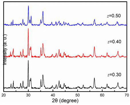
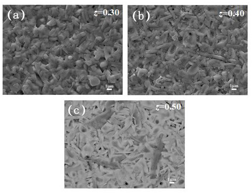
[0004] The purpose of the present invention is to overcome the problems of narrow sintering temperature range of pyroxene structure silicate compound, difficulty in forming porcelain, and large negative resonance frequency temperature coefficient, and provide a low dielectric constant silicate microwave dielectric ceramic and its preparation method, the main crystal phase of the cermet is pyroxene structure Ca 1-x-y / 2 A x Mg 1-y / 2 B y Si 3 o 9 solid solution phase and Ba 5 Si 8 o 21 Phase, with low cost, low dielectric constant, low dielectric loss, good temperature stability, excellent reduction resistance, wide sintering temperature range, and stable preparation process

Method used


Image

  • Silicate microwave dielectric ceramic with low dielectric constant and preparation method thereof
  • Silicate microwave dielectric ceramic with low dielectric constant and preparation method thereof
  • Silicate microwave dielectric ceramic with low dielectric constant and preparation method thereof

Examples


Embodiment 1

[0025] Step 1, Synthetic Ca 1-x-y / 2 A x Mg 1-y / 2 B y Si 3 o 9 Powder: with CaCO 3 、BaCO 3 , SrCO 3 , Mg(OH) 2 4MgCO 3 ·5H 2 O, ZnO, CoO, MnO, and SiO 2 The powder is the raw material, according to the chemical expression, it is Ca 1-x-y / 2 A x Mg 1-y / 2 B y Si 3 o 9 (A=Sr, Ba; B=Zn, Co, Mn; 0.02≤ x ≤0.10; 0.10≤ y ≤0.50) to form a mixed powder by weighing and batching, wet ball milling for 12 hours, dried and placed in an alumina crucible, and pre-fired in a high-temperature box-type electric furnace at 1050 ° C for 2 hours to obtain Ca 1-x-y / 2 A x Mg 1-y / 2 B y Si 3 o 9 Powder;

[0026] Step 2, synthesis of Ba 5 Si 8 o 21 Powder: with BaCO 3 and SiO 2 Powder is the raw material, according to the chemical expression Ba 5 Si 8 o 21 Weigh the ingredients to form a mixed powder, wet ball mill for 12 hours, put it in an alumina crucible after drying, and pre-fire it in a high-temperature box-type electric furnace at 1050 ° C for 3 hours to obtain Ba...

Embodiment 2

[0034] Step 1, Synthetic Ca 1-x-y / 2 A x Mg 1-y / 2 B y Si 3 o 9 Powder: with CaCO 3 、BaCO 3 , SrCO 3 , Mg(OH) 2 4MgCO 3 ·5H 2 O, ZnO, CoO, MnO, and SiO 2 The powder is the raw material, according to the chemical expression, it is Ca 1-x-y / 2 A x Mg 1-y / 2 B y Si 3 o 9 (A=Sr, Ba; B=Zn, Co, Mn; 0.02≤ x ≤0.10; 0.10≤ y ≤0.50) to form a mixed powder by weighing and batching, wet ball milling for 12 hours, dried and placed in an alumina crucible, and pre-fired in a high-temperature box-type electric furnace at 11150 ° C for 6 hours to obtain Ca 1-x-y / 2 A x Mg 1-y / 2 B y Si 3 o 9 Powder;

[0035] Step 2, synthesis of Ba 5 Si 8 o 21 Powder: with BaCO 3 and SiO 2 Powder is the raw material, according to the chemical expression Ba 5 Si 8 o 21 Weigh the ingredients to form a mixed powder, wet ball mill for 12 hours, put it in an alumina crucible after drying, and pre-fire it in a high-temperature box-type electric furnace at 1150 ° C for 5 hours to obtain Ba ...

Embodiment 3

[0043] Step 1, Synthetic Ca 1-x-y / 2 A x Mg 1-y / 2 B y Si 3 o 9 Powder: with CaCO 3 、BaCO 3 , SrCO 3 , Mg(OH) 2 4MgCO3 ·5H 2 O, ZnO, CoO, MnO, and SiO 2 The powder is the raw material, according to the chemical expression, it is Ca 1-x-y / 2 A x Mg 1-y / 2 B y Si 3 o 9 (A=Sr, Ba; B=Zn, Co, Mn; 0.02≤ x ≤0.10; 0.10≤ y ≤0.50) to form a mixed powder by weighing and batching, wet ball milling for 12 hours, dried and placed in an alumina crucible, and pre-fired in a high-temperature box-type electric furnace at 1100 ° C for 4 hours to obtain Ca 1-x-y / 2 A x Mg 1-y / 2 B y Si 3 o 9 Powder;

[0044] Step 2, synthesis of Ba 5 Si 8 o 21 Powder: with BaCO 3 and SiO 2 Powder is the raw material, according to the chemical expression Ba 5 Si 8 o 21 Weigh the ingredients to form a mixed powder, wet ball mill for 12 hours, put it in an alumina crucible after drying, and pre-fire it in a high-temperature box-type electric furnace at 110°C for 4 hours to obtain Ba 5 S...


PUM

PropertyMeasurementUnit
particle sizeaaaaaaaaaa

Abstract

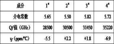
The invention discloses a low dielectric constant silicate microwave dielectric ceramic and a preparation method thereof, the chemical expression of the ceramic is Ca < 1-x-y / 2 > A < x > Mg < 1-y / 2 > B < y > Si < 3 > O < 9-z > Ba5Si < 8 > O < 21 >, b is Zn, Co or Mn; 0.02 < = x < = 0.10; 0.10 < = y < = 0.50; 0.30 < = z < = 0.50. The preparation process of the ceramic material sequentially comprises the following steps: synthesizing Ca (1-x-y) / 2AxMg (1-y) / 2BySi3O9 powder, synthesizing Ba5Si8O21 powder, preparing composite powder, carrying out ball milling, and carrying out DCS (distributed control system) rapid sintering to obtain the ceramic. On one hand, the Qf value of a CaMgSi3O9 crystal phase is improved through trace Sr ion substitution, on the other hand, Mn ions are obtained through Zn or Co to co-replace A and B sites to regulate and control the layered structure of the CaMgSi3O9 structure, and then the Qf value and the tau f value of the CaMgSi3O9 structure are regulated and controlled. In addition, the dielectric constant of the prepared Ca < 1-x-y / 2A < x > Mg < 1-y / 2B < y > Si < 3 > O < 9-z > Ba5Si < 8 > O < 21 > ceramic material is 5.5-8.2, the Qf value is 28500-76450 GHz, the tau < f > value is within + / -15 ppm / DEG C, the preparation process is simple, the preparation period is short, the process stability is good, the anti-reduction characteristic is good, a base metal inner electrode can resist reduction atmosphere sintering, and the ceramic material is suitable for manufacturing a temperature compensation type MLCC capacitor.

Description

technical field [0001] The invention belongs to the field of microwave dielectric ceramics, in particular to a low dielectric constant silicate microwave dielectric ceramic and a preparation method thereof. Background technique [0002] With the gradual development of communication technology in the direction of millimeter waves, MLCC has higher and higher requirements for the microwave dielectric properties of dielectric materials, requiring them to have a low dielectric constant (ε r <10) to improve the information transmission rate of the device, lower high-frequency dielectric loss (tanδ<0.001, f =10GHz) to enhance its frequency selection and reduce energy consumption, near zero resonant frequency temperature coefficient ( τ f ~±10ppm / ℃) to ensure the stability of the signal during resonance and transmission. At present, the research work of low dielectric constant materials at home and abroad is mainly concentrated on Al 2 o 3 , Mg 2 SiO 4 , AWO4 (A=Ca, Sr,...

Claims


Application Information

Patent Timeline
Patent Type & Authority Applications(China)
IPC IPC(8): C04B35/16C04B35/622
CPCC04B35/16C04B35/622C04B2235/442C04B2235/3206C04B2235/3284C04B2235/3275C04B2235/3262C04B2235/3418C04B2235/6562C04B2235/6567C04B2235/96
Inventor 吕学鹏
Owner NANJING INST OF TECH
Why Eureka
Eureka Blog
Learn More