
Surgical robot navigation plate and navigation method

A surgical robot and navigation board technology, applied in surgical navigation systems, surgical robots, computer-aided planning/modeling, etc., can solve the problems of inability to locate and correct the central area of ​​the navigation board, unstable operation of the surgical robot system, and inability to track living objects in time Targets and other issues, to achieve the effect of high automation, low computing power requirements, and high precision

Active Publication Date: 2022-04-29
ZHUHAI WEIERKANG BIOTECH
View PDF16 Cites 2 Cited by
  • Summary
  • Abstract
  • Description
  • Claims
  • Application Information

AI Technical Summary

Problems solved by technology

[0002] Traditional surgical robot navigation uses preoperative planning, combined with intraoperative X-ray image fusion and matching measurement technology, combined with real-time optical image tracking technology, the use of this navigation technology requires a computer with powerful computing power to track the movement of the target (target) in time , to prevent the movement of the robot from lagging, but the computing power of the existing computer system is limited, resulting in such a situation that the lag is often caused by the movement of the living target, and the target cannot be tracked in time. The operation of the entire surgical robot system is unstable or even the tracking registration fails.
Patent CN201811069744.3 discloses a flexible positioning device and navigation method suitable for robot surgical navigation under X-rays. It needs third-party infrared positioning equipment to assist the robot in navigation, which is complicated and costly to operate. In addition, the navigation board is only set around The target point is corrected, and the positioning and correction of the middle area of ​​the navigation board cannot be performed, and the scope of application is narrow

Method used


Image

  • Surgical robot navigation plate and navigation method
  • Surgical robot navigation plate and navigation method
  • Surgical robot navigation plate and navigation method

Examples


Embodiment Construction

[0046] Below, in conjunction with accompanying drawing and specific embodiment, the present invention is described further:

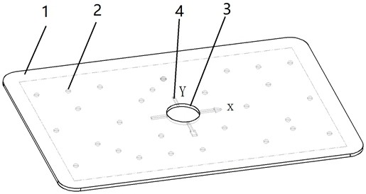
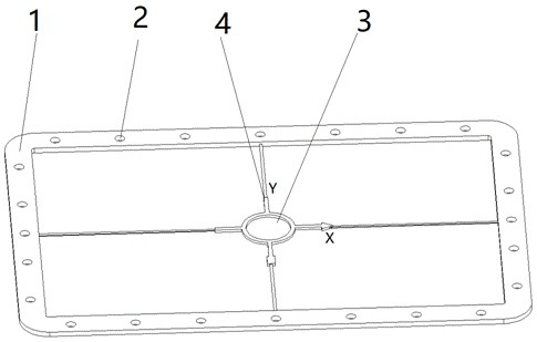
[0047] The invention discloses a surgical robot navigation board, which comprises a navigation board body, an outer frame 1 is arranged around the navigation board body, a plurality of correction target points 2 are distributed on the navigation board body, and a center of the navigation board body is opened. There is a central correction target. And discloses a method of using the navigation board as a guide, correcting and tracking the surgical robot, by using the navigation board as an intermediate bridge, the stable tissue structure image obtained by the intraoperative X-ray is matched with the preoperative MRI image and unified with the robot Coordinate system, use the unified coordinate system to guide the robot to perform positioning, and guide the robot vision system to complete the tracking and positioning in the operation through the navigatio...


PUM


Abstract

The invention discloses a surgical robot navigation plate which comprises a navigation plate body, an outer frame is arranged on the periphery of the navigation plate body, a plurality of correction target spots are distributed on the navigation plate body, and a center correction target spot is formed in the center of the navigation plate body. The invention also discloses a method for guiding, correcting and tracking a surgical robot by using the navigation plate, the navigation plate is used as a middle bridge, a stable tissue structure image obtained by X-ray in an operation is matched with a pre-operation MRI image, a unified coordinate system is established with the robot, the unified coordinate system is used for guiding the robot to carry out positioning, and the positioning accuracy is improved. And the robot vision system is guided by the navigation plate to complete tracking and positioning in the operation. The method does not need third-party special navigation equipment commonly used at present, and has the advantages of being not shielded, simple, mature and stable in algorithm, low in cost, simple and easy to operate and learn, stable in system, high in flexibility, strong in expansibility, wide in application range, faster and higher in precision.

Description

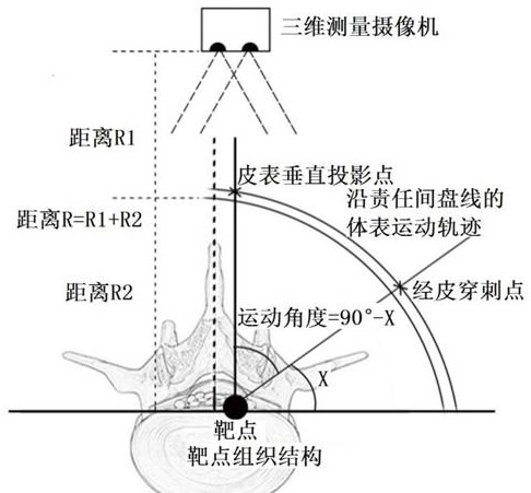
technical field [0001] The invention relates to a surgical robot navigation board, in particular to a surgical robot navigation board and a navigation method. Background technique [0002] Traditional surgical robot navigation uses preoperative planning, combined with intraoperative X-ray image fusion and matching measurement technology, combined with real-time optical image tracking technology, the use of this navigation technology requires a computer with powerful computing power to track the movement of the target (target) in time , to prevent the robot from lagging behind, but the computing power of the existing computer system is limited, resulting in such a lag often due to the movement of the living target, the situation that the target cannot be tracked in time, the operation of the entire surgical robot system is unstable, and even the tracking registration fails. Patent CN201811069744.3 discloses a flexible positioning device and navigation method suitable for robo...

Claims


Application Information

Patent Timeline
Patent Type & Authority Applications(China)
IPC IPC(8): A61B34/20A61B34/30A61B34/10A61B17/34
CPCA61B34/20A61B34/30A61B34/10A61B17/3403A61B2034/2065A61B2034/2051A61B2034/2063A61B2034/2068A61B2034/108
Inventor 胡善云梁泳强丘永洪周琪肖伟鹏
Owner ZHUHAI WEIERKANG BIOTECH
Learn More