Eureka AIR delivers breakthrough ideas for toughest innovation challenges, trusted by R&D personnel around the world.

Heart temporary pacemaker fixing device with massage function

A technology of fixing device and pacemaker, which is applied in the directions of cardiac stimulators, kneading massage appliances, massage auxiliary products, etc., can solve the problems of reducing the convenience of use, the influence of users, and reducing flexibility, so as to prevent the catheter from shaking. The effect of removing, protecting the physical condition, and improving the patient's condition

Inactive Publication Date: 2022-04-29
THE FIRST AFFILIATED HOSPITAL OF ANHUI MEDICAL UNIV
View PDF1 Cites 0 Cited by
  • Summary
  • Abstract
  • Description
  • Claims
  • Application Information

AI Technical Summary

Problems solved by technology

[0003] The Chinese patent with the application number CN202120149701.7 discloses a temporary cardiac pacemaker fixing device, which relates to the technical field of cardiac temporary pacemakers, in order to solve the inconvenience of the existing temporary cardiac pacemaker fixing device after use Replacing a clean fixed component leads to the growth of a large number of bacteria on its upper end, which affects users
Both sides of the main body bracket are equipped with elastic nylon cloth, the elastic nylon cloth is fixedly connected with the main body bracket, and the upper end of the elastic nylon cloth is equipped with a fixed bracket, and the fixed bracket is fixedly connected with the elastic nylon cloth. A cooling fan is installed inside the fixed bracket, and the cooling fan is fixedly connected with the fixed bracket, and the front and rear ends of the elastic nylon cloth away from the side of the main body bracket are all equipped with connecting fixing buckles, and the connecting fixing buckles are fixed with the elastic nylon cloth connection, the side of the connection fixing buckle away from the main body bracket is equipped with a butt joint, and the front and rear ends of the connection fixing buckle are equipped with anti-off springs. The fixing device of the temporary cardiac pacemaker disclosed in this patent does not have a massage Function, thus unable to promote blood circulation, unable to improve the blood supply capacity of the auxiliary heart pump, thus unable to relieve the patient's condition, at the same time, it does not have massage function, and the adverse effect caused by the compression of the patient's legs during the wearing process of the fixation device It cannot be eliminated, and the position of the temporary cardiac pacemaker cannot be changed, thereby reducing the flexibility of use. At the same time, the position of the temporary cardiac pacemaker cannot be changed, which is not conducive to the patient's action, and it will be a temporary cardiac pacemaker for the medical staff to view data inconvenience
[0004] However, there are great defects in the existing temporary cardiac pacemaker fixing device during use. The existing temporary cardiac pacemaker fixing device does not have a massage function, and then cannot promote blood circulation, and cannot improve the function of assisting and strengthening the heart pump. Therefore, it cannot relieve the patient's condition. At the same time, it does not have a massage function. The adverse effects caused by the compression of the patient's legs during the wearing process of the fixing device cannot be eliminated. The existing temporary cardiac pacemaker fixing device cannot be changed. The position of the temporary cardiac pacemaker reduces the flexibility of use. At the same time, the position of the temporary cardiac pacemaker cannot be changed, which is not conducive to the patient's action, and it will cause inconvenience for the medical staff to view the temporary cardiac pacemaker data. The installation of the existing temporary cardiac pacemaker fixing device and the fixing of the temporary cardiac pacemaker are cumbersome, which reduces the convenience of use

Method used


Image

  • Heart temporary pacemaker fixing device with massage function
  • Heart temporary pacemaker fixing device with massage function
  • Heart temporary pacemaker fixing device with massage function

Examples


Embodiment Construction

[0035] In order to make the technical means, creative features, goals and effects achieved by the present invention easy to understand, the present invention will be further described below in conjunction with specific embodiments.

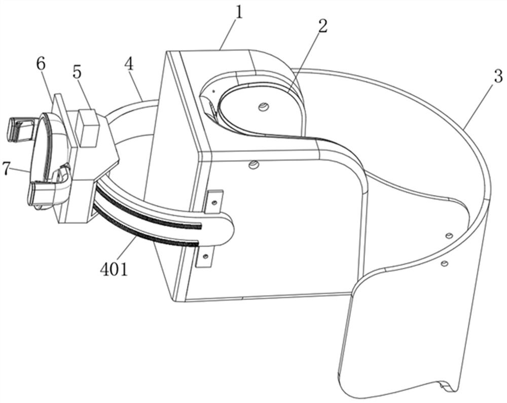
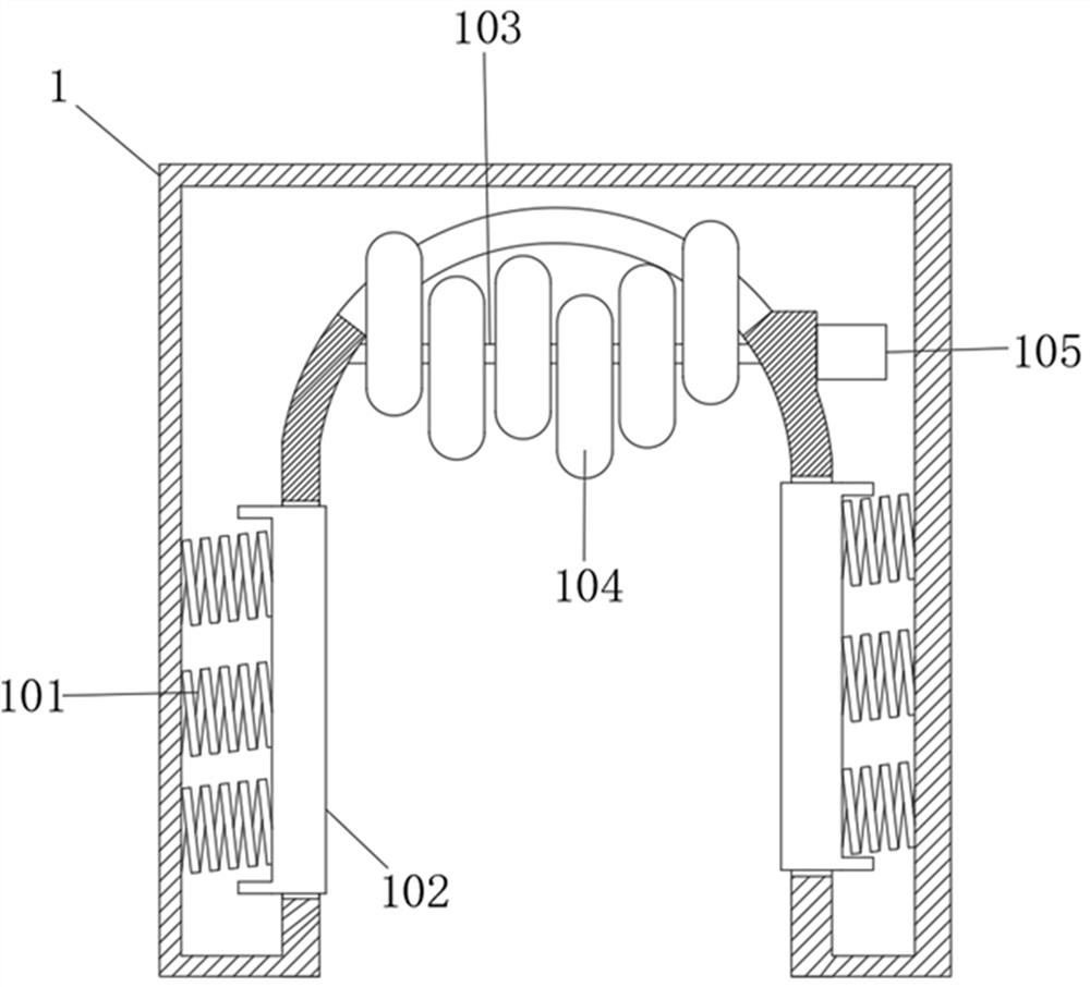
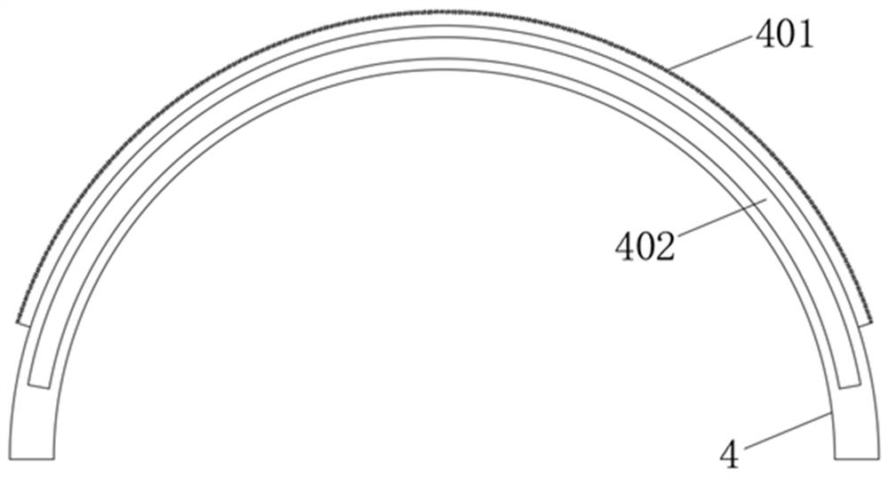
[0036] Such as Figure 1-Figure 9 As shown, a temporary cardiac pacemaker fixing device with a massage function according to the present invention includes a fixing ferrule 1, a fixing plate 4, a mounting frame 5 and a clamping assembly 7, and the cross section of the fixing ferrule 1 is " U"-shaped structure, both ends of one end of the fixed ferrule 1 are fixed with elastic Velcro straps 3, the two elastic Velcro straps 3 can be bonded to each other, the fixed plate 4 is a semi-circular structure, and the fixed plate 4 is located on the fixed The ferrule 1 is away from one end of the elastic Velcro strap 3 and the two ends of the fixed plate 4 are respectively fixed to the two side walls of the fixed ferrule 1. The fixed plate 4 is movable with ...


PUM


Abstract

The invention relates to the technical field of heart temporary pacemaker fixing, in particular to a heart temporary pacemaker fixing device with a massage function, which comprises a fixing clamping sleeve, a fixing plate, a mounting frame and a clamping assembly, and is characterized in that the fixing plate and the mounting frame are used, and the mounting frame is movably matched on the fixing plate; the device can be driven by the moving driving motor, and the position of the heart temporary pacemaker on the clamping assembly is adjusted. The device has the advantages that fixation is stable, use is flexible, and medical staff can check set pacing parameters conveniently. Besides, for a temporary pacemaker implantation patient without lower limb braking, the device is convenient for the patient to flexibly move when the patient wears the heart temporary pacemaker, and for a patient with lower limb braking, the device also has the effects of massaging the lower limb, promoting blood circulation of the lower limb and preventing venous thrombosis.

Description

technical field [0001] The invention relates to the technical field of temporary cardiac pacemaker fixing, in particular to a temporary cardiac pacemaker fixing device with a massage function. Background technique [0002] Temporary cardiac pacing is a temporary or temporary artificial cardiac pacing with non-permanent implantation of pacing leads. Any patient with acute hemodynamic changes caused by bradycardia and / or brief asystole A temporary cardiac pacemaker should be considered. Implantation through the right femoral vein is one of the common implantation methods of temporary pacemakers. After implantation in this way, patients are usually required to immobilize their right lower limbs for 1-2 weeks, and the pulse of the temporary pacemaker needs to be controlled by a fixed device. The transmitter is fixed to prevent the line from being discounted and the electrode lead to be damaged or broken, so as to ensure the stable use of the temporary cardiac pacemaker. [000...

Claims


Application Information

Patent Timeline
Patent Type & Authority Applications(China)
IPC IPC(8): A61N1/362A61N1/372A61N1/375A61H7/00A61H9/00
CPCA61N1/362A61N1/372A61N1/375A61N1/37512A61H7/00A61H9/0078A61H9/0092A61H2201/1642A61H2205/10A61H2209/00
Inventor 王晓灿韩江英吕冶芳吴银霞张玲吴亚丽董慧凝栾贝贝
Owner THE FIRST AFFILIATED HOSPITAL OF ANHUI MEDICAL UNIV
Why Eureka
Eureka Blog
Learn More