Polluted soil remediation equipment based on ex-situ chemical leaching

A technology for chemical leaching and polluted soil, applied in the field of soil remediation, can solve the problems of reduced soil remediation efficiency, troublesome soil cleaning, and reduced soil remediation efficiency, and achieve the effect of improving spraying effect, improving contact efficiency, and efficient turning

Active Publication Date: 2022-04-29
重庆渝隆环保有限公司
View PDF5 Cites 0 Cited by
  • Summary
  • Abstract
  • Description
  • Claims
  • Application Information

AI Technical Summary

Problems solved by technology

[0004] The object of the present invention is to provide a kind of contaminated soil remediation equipment based on ex-situ chemical leaching to solve the above-mentioned background technology. In order to ensure the sufficiency of soil remediation, in the purification process of a single operation of the equipment, the specified amount of soil will be To carry out the corresponding spray repair, before carrying out subsequent batches of soil repair, it is necessary to clean up the corresponding containing structure in the equipment to avoid the problem of lower efficiency of subsequent soil repair due to incomplete cleaning, and because the soil is being After spraying the solution, it is in a relatively diluted state. Although the soil discharged after remediation has special equipment for secondary treatment, it is very troublesome to clean up the remaining diluted soil, which greatly reduces the efficiency of soil remediation.

Method used


Image

  • Polluted soil remediation equipment based on ex-situ chemical leaching
  • Polluted soil remediation equipment based on ex-situ chemical leaching
  • Polluted soil remediation equipment based on ex-situ chemical leaching

Examples


no. 1 example

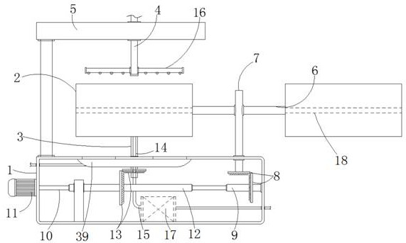
[0033] Such as figure 1 As shown, the restoration equipment includes a base 1 and a storage box 2, the storage box 2 is used to accommodate soil particles, the storage box 2 is located above the base 1, and the top of the storage box 2 is provided with a frame 5 installed on the upper end surface of the base 1, The bottom and top of the containing box 2 are respectively provided with a cleaning rod 3 and a spraying rod 4, and also includes a partition 18, which is horizontally fixed at the middle position inside the containing box 2, and the containing box 2 is evenly divided into upper and lower parts. The space for accommodating soil particles, and the accommodating box 2 is a structure with upper and lower openings, and the accommodating box 2 is installed on the upper half of the vertical axis 7 through the rotation of the horizontal axis 6, and the vertical axis 7 installed in the upper wall on the right side of the base 1 is rotated The bottom end is connected to the fir...

no. 2 example

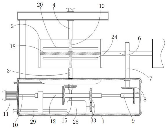
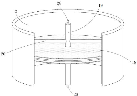
[0037] Different from the first embodiment, the sprinkler assembly in this embodiment includes a driving device and a sprinkler device, and the sprinkler device is composed of a core rod 19 and a first cross bar 20, and the core rod 19 is installed at the center of the dividing plate 18 , the vertically distributed core rod 19 and the horizontally distributed first cross bar 20 are respectively provided with a third cavity 23 and a second cavity 22 connected to each other, and the second cavity 22 and the lower end surface of the first cross bar 20 The spray hole 21 is connected, and the third cavity 23 is connected with the inner cavity of the spray rod 4, and the spray rod 4, which is rotatably installed on the frame 5, is connected with the water pipe at the output end of the water pump, and the water pump passes through the spray rod 4. The spray liquid is sprayed out through the third cavity 23, the second cavity 22 and the spray hole 21, and the wetting operation is perfo...

no. 3 example

[0041] As an additional technical solution in this application, in order to ensure that metal impurities that are not fully screened in the soil will not affect the subsequent backfilling of the soil, the separator 18 in this embodiment includes the outermost elastic layer 36, with Based on the reinforced filling layer 35 and the electromagnetic plate 34 located at the center, the electromagnetic plate 34 is energized to generate magnetism for absorbing unscreened metal particles mixed in the soil.

[0042] As a further step, in the filling layer 35 in this embodiment, there is also a slideway 37 that penetrates up and down. Be connected with magnetic block 38, and the surface corresponding to magnetic block 38 and the electromagnetic plate 34 after energization is mutually repulsive setting, when electromagnetic plate 34 carries out intermittent power on and off, as Figure 8 As shown, the magnetic block 38 will correspondingly slide in the slideway 37 at high frequency, and ...


PUM


Abstract

The contaminated soil remediation equipment based on ex-situ chemical leaching comprises a base and a containing box, a first transverse cylinder rotationally installed in the base is rotationally installed at the right end of a rotating shaft in a one-way mode through a one-way bearing, and the rotating shaft located in the base is connected with a motor; and a second transverse cylinder is also rotationally mounted on the rotating shaft in a one-way manner. According to the contaminated soil remediation equipment based on ex-situ chemical leaching, the containing box is designed into an upper containing space and a lower containing space, and the other used space can be synchronously cleaned while soil in one space is sprayed in a self-rotation mode; and meanwhile, switching use of different containing boxes and cleaning of the containing boxes can be achieved through the same power source, space division is achieved through partition plates, and meanwhile separation of metal impurities and improvement of the spraying effect can be achieved through operation of internal electromagnetic plates.

Description

technical field [0001] The invention relates to the technical field of soil remediation, in particular to a contaminated soil remediation device based on ex-situ chemical leaching. Background technique [0002] The ectopic chemical leaching method refers to digging out the contaminated soil from the ground, and after simple screening and removal of impurities, it is transported to the corresponding spraying equipment, and the chemical solution and the soil are sprayed by spraying. The heavy metals and oil pollution components in the soil are in contact with the soil, and the soil is backfilled after the purification is completed. Therefore, the existing similar repair equipment based on the ex-situ chemical leaching method has the following problems in actual use: [0003] In order to ensure the adequacy of soil remediation, in the purification process of a single operation of the equipment, the specified amount of soil will be sprayed and repaired accordingly. to avoid the...

Claims


Application Information

Patent Timeline
Patent Type & Authority Applications(China)
IPC IPC(8): B09C1/02B09C1/00B09C1/08
CPCB09C1/02B09C1/00B09C1/08
Inventor 丁坛峰
Owner 重庆渝隆环保有限公司
Why Eureka
Try Eureka