Anti-falling flap wheel and production process thereof
A louver wheel and anti-shedding technology, which is applied in the direction of manufacturing tools, metal processing equipment, and fixed grinding wheel devices, can solve the problems of blade wear, shedding, and loose parts, so as to prolong the service life and improve the wear resistance. The effect of abrasion resistance
- Summary
- Abstract
- Description
- Claims
- Application Information
AI Technical Summary
Problems solved by technology
Method used
Image
Examples
Embodiment 1
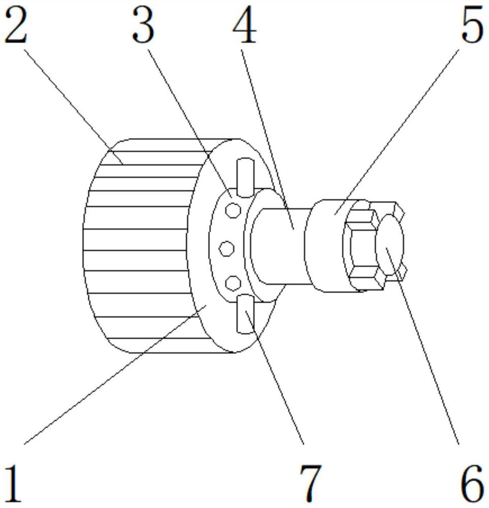
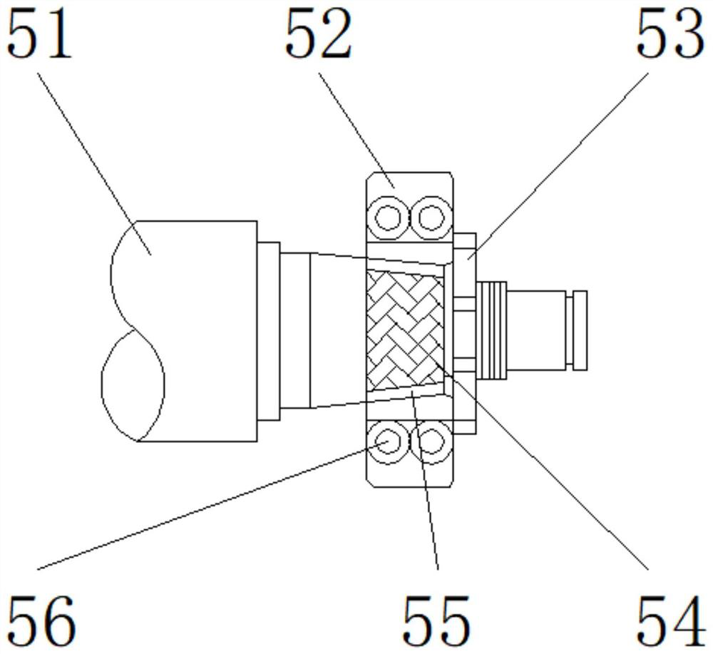
[0030] Such as Figure 1-5 As shown, the present invention provides an anti-falling louver, including a main body 1, which is characterized in that: the outer wall of the main body 1 is provided with a protective device 2, one side of the main body 1 is provided with a chassis 3, and the anti-falling device 7 runs through the chassis 3. One side of the chassis 3 is provided with a rotating shaft 4, one side of the rotating shaft 4 is provided with an auxiliary locking device 5, and one side of the auxiliary locking device 5 is provided with a mounting groove 6; the auxiliary locking device 5 includes a connecting shaft 51, a taper Bearing 52, lock nut 53, sheath 54, repairing material 55, four-side positioning bolt 56, taper bearing 52 is positioned at the side of connecting shaft 51, and lock nut 53 is positioned at the side of taper bearing 52; Lock nut 53 and Thread grooves are arranged between the taper bearings 52, one side of the lock nut 53 is detachably connected to on...
Embodiment 2
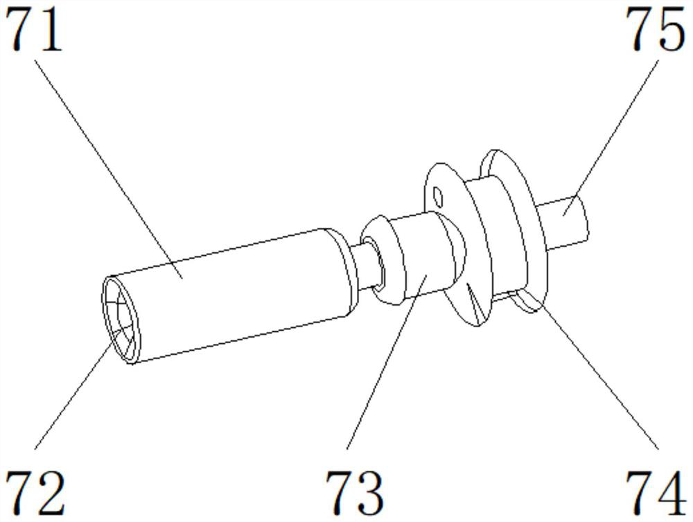
[0033] Such as Figure 1-5 As shown, on the basis of Embodiment 1, the present invention provides a technical solution: preferably, the anti-falling device 7 includes a bearing 71, a bearing hole 72, a limit cylinder 73, a tray 74, a fixed connecting rod 75, and a bearing hole 72 Located inside the bearing 71, the limit cylinder 73 is located on one side of the bearing 71, the tray 74 is located on one side of the limit cylinder 73, the fixed link 75 is located on one side of the tray 74, and the tray 74 and the fixed link 75 are arranged There is a notch, one side of the tray 74 is detachably connected to one side of the fixed link 75 through the notch, a connecting hole is arranged between the tray 74 and the limiting cylinder 73, and one side of the limiting cylinder 73 is connected to the tray through the connecting hole. The other side of 74 is fixedly connected, and a slot is provided between the limiting cylinder 73 and the bearing 71 , and the other side of the limitin...
Embodiment 3
[0036] Such as Figure 1-5As shown, on the basis of Example 1, the present invention provides a technical solution: preferably, the protective device 2 includes an epoxy resin coating 21, a wear-resistant particle coating 22, a soft bearing surface coating 23, an erosion-resistant Wear coating 24, wear-resistant particle coating 22 is positioned at the upper end of epoxy resin coating 21, and soft bearing surface coating 23 is positioned at the upper end of wear-resistant particle coating 22, and erosion-resistant wear coating 24 is positioned at the epoxy resin coating The lower end of 21 is provided with superglue between the erosion-resistant and wear-resistant coating 24 and the epoxy resin coating 21, and the lower end of the epoxy-resin coating 21 is fixedly connected with the upper end of the erosion-resistant and wear-resistant coating 24 through superglue. A fixing glue is arranged between the supporting surface coating 23 and the wear-resistant grain coating 22 , and...
PUM
 Abstract
Description
Claims
Application Information
 - R&D
- Intellectual Property
- Life Sciences
- Materials
- Tech Scout
- Unparalleled Data Quality
- Higher Quality Content
- 60% Fewer Hallucinations
Browse by: Latest US Patents, China's latest patents, Technical Efficacy Thesaurus, Application Domain, Technology Topic, Popular Technical Reports.
© 2025 PatSnap. All rights reserved.Legal|Privacy policy|Modern Slavery Act Transparency Statement|Sitemap|About US| Contact US: help@patsnap.com


