Method for fixing carbon fiber product

A fixing method and carbon fiber technology, applied in metal processing and other directions, can solve problems such as poor installation and positioning accuracy, scrapping, and low processing efficiency, and achieve the effects of avoiding adsorption and positioning, reducing manufacturing costs, and improving processing quality

Pending Publication Date: 2022-04-29
JIANGSU AOSHENG COMPOSITE MATERIALS HI TECH
0 Cites 0 Cited by

AI-Extracted Technical Summary

Problems solved by technology

Carbon fiber composite materials are widely used in aerospace, rail transit, automobile, medical and other fields due to their light specific gravity, high specific strength, and good fatigue resistance. However, carbon fiber composite materials and carbon fiber composite components have high precision and high quality. Requirements, making processing a key task. In the quality control of processing and cutting, the adsorption capacity becomes one of the important parameters. If the carbon fiber composite material or carbon fiber composite component cannot be stably adsorbed before processing, it will cause it during processing and cutting. Shaking and making the product scrapped
[0003] At present, carbon fiber products, especially products with sp...

Method used

According to the size of each area on the product 1, determine the distance from the cutting edge of the product 1 when the sucker 3 is adsorbed on the product 1, when a certain area of ​​the product 1 is larger, it can be suitably farther, and utilize the product 1 self property to eliminate the cutting stress . When the product 1 has a square area with a side length ≥ 300mm, the distance between the suction cup 3 on the product 1 and the edge to be cut of the product 1 is 20-40mm; when the product 1 side length ≤ 300mm, the suction cup 3 is in the The distance between the position of adsorption on product 1 and the edge to be cut of product 1 is 15-25mm. For the overlapped parts, choose whether to refine according to the cutting accuracy requirements of product 1. If the cutting accuracy requirements are not high, the overlapping parts can be selected arbitrarily, and the flexibility is higher. When the cutting accuracy requirements of product 1 are relatively high, the specific It should be: when the product 1 has a square area with a side length ≥ 300mm, the distance between the suction cup 3 on the product 1 and the edge to be cut of the product 1 is 22-40mm; when the side length of the product 1 is < 300mm, The distance between the suction cup 3 on the product 1 and the edge of the product 1 to be cut is 15-22 mm.
As shown in Figure 5-7, the peripheral surface of the insertion direction of locator 4 is a tapered surface, and the side wall surface of positioning groove 5 is matched with the peripheral surface of the insertion direction of locator 4, and the operation during insertion is simplified and can Make sure...

Abstract

The invention relates to a method for fixing a carbon fiber product, which is used for fixing the carbon fiber product to be cut and processed by adopting a fixing jig and adopting at least one of suction cup adsorption and positioning piece positioning. The distance between the suction positions of the suction cups on the product and the to-be-cut edge of the product and the distance between the suction cups are determined, the shapes of the suction cups and the sizes of cup openings of the suction cups are selected, the suction cups are arranged on a fixing jig, and the product is sucked to the arranged suction cups; the positioning of the positioning pieces comprises the steps that according to the shape of the product, a plurality of positioning pieces are arranged on the product, positioning grooves matched with the positioning pieces in shape and position are formed in the fixing jig, and the positioning pieces of the product are inserted into the corresponding positioning grooves, so that the problems of adsorption and positioning during processing of the carbon fiber product are solved, and the processing quality of the carbon fiber product is greatly improved; and the production yield is improved, so that the manufacturing cost of the carbon fibers is reduced.

Application Domain

Metal working apparatus

Technology Topic

Manufacturing engineeringFiber +3

Image

  • Method for fixing carbon fiber product
  • Method for fixing carbon fiber product
  • Method for fixing carbon fiber product

Examples

  • Experimental program(1)

Example Embodiment

[0035] The technical solutions of the present invention will be clearly and completely described below with reference to the accompanying drawings. Obviously, the described embodiments are a part of the embodiments of the present invention, but not all of the embodiments. Based on the embodiments of the present invention, all other embodiments obtained by those of ordinary skill in the art without creative efforts shall fall within the protection scope of the present invention.
[0036] In the description of the present invention, it should be noted that the terms "center", "upper", "lower", "left", "right", "vertical", "horizontal", "inner", "outer", etc. The indicated orientation or positional relationship is based on the orientation or positional relationship shown in the accompanying drawings, and is only for the convenience of describing the present invention and simplifying the description, rather than indicating or implying that the indicated device or element must have a specific orientation or a specific orientation. construction and operation, and therefore should not be construed as limiting the invention. Furthermore, the terms "first", "second", and "third" are used for descriptive purposes only and should not be construed to indicate or imply relative importance.
[0037] In the description of the present invention, it should be noted that the terms "installed", "connected" and "connected" should be understood in a broad sense, unless otherwise expressly specified and limited, for example, it may be a fixed connection or a detachable connection Connection, or integral connection; can be mechanical connection, can also be electrical connection; can be directly connected, can also be indirectly connected through an intermediate medium, can be internal communication between two elements. For those of ordinary skill in the art, the specific meanings of the above terms in the present invention can be understood in specific situations.
[0038] like figure 2 , 7 As shown, a method for fixing a carbon fiber product is used for fixing a carbon fiber product to be cut, so as to ensure the stability of the carbon fiber product during cutting and ensure cutting accuracy. The fixing method adopts the fixing jig 2 , and adopts at least one of the suction cup 3 adsorption and the positioning member 4 positioning for fixing, and the to-be-processed product 1 is fixed on the fixing jig 2 . The suction method of the suction cup 3 includes: according to the size and shape of the product 1, determining the distance between the suction position of the suction cup 3 on the product 1 and the to-be-cut edge of the product 1 and the distance between the suction cups 3, and selecting the shape of the suction cup 3, After the size of the mouth 31 of the suction cup 3 and the position, shape and size of the suction cup 3 are determined, the suction cup 3 is set on the fixture 2, and the product 1 is adsorbed on the set suction cup 3. The positioning method of the positioning member 4 includes: according to the shape of the product 1, a plurality of positioning members 4 are arranged on the product 1, and a positioning groove 5 matching the shape and position of the positioning member 4 is opened on the fixing jig 2, and the The positioning member 4 is inserted into the corresponding positioning groove 5 . The suction of the suction cup 3 and the positioning of the positioning member 4 can cooperate with each other. When the suction cup 3 adsorption and the positioning of the positioning member 4 are used at the same time, the suction cup 3 and the positioning groove 5 are arranged on the same fixture 2, and the positioning of the positioning member 4 can ensure the suction of the suction cup 3. The accuracy of the position, the adsorption requirements of different positions of the product 1 are different, and the adsorption of the suction cup 3 can ensure that the product 1 can be stably fixed on the fixture 2.
[0039] The surface of the fixing jig 2 has a profiling surface with the same shape as the surface of the product 1. The surface of the product 1 and the surface of the fixing jig 2 can be just close to each other with a slight gap through the suction of the suction cup 3 and the positioning of the positioning member 4.
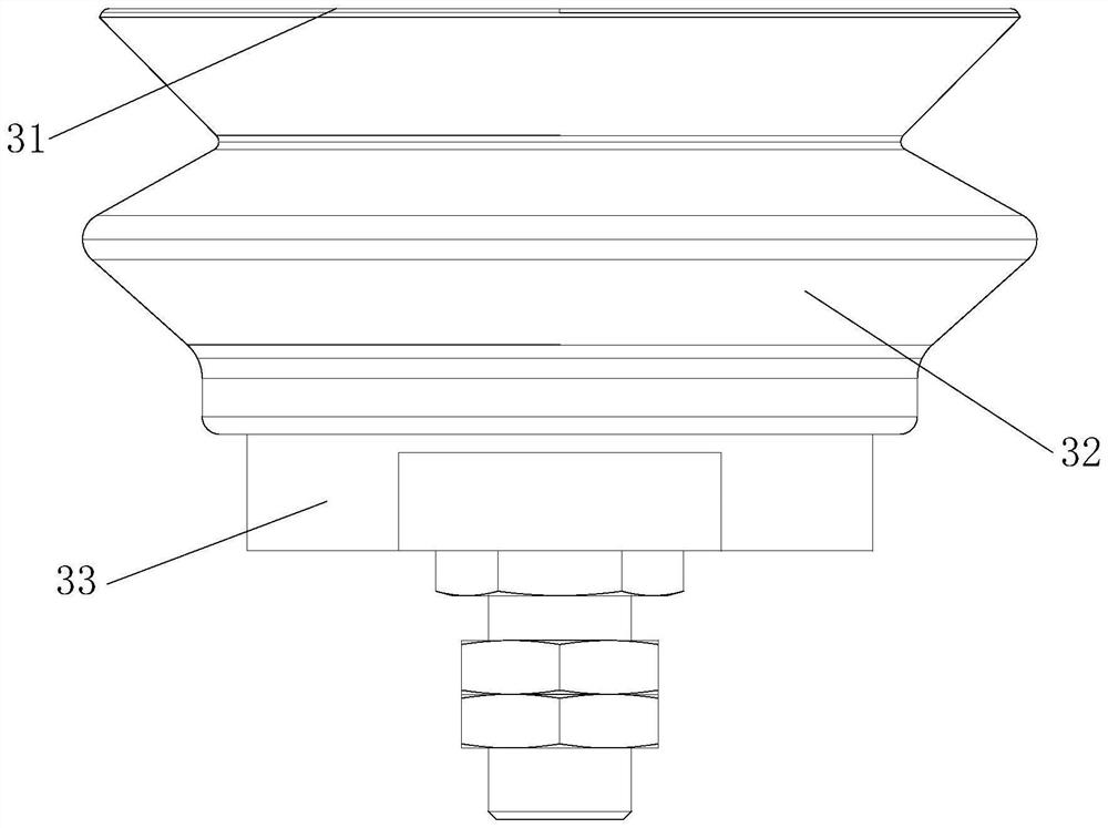
[0040] like Figure 1-3 As shown, the adsorption method of the suction cup 3 mainly solves the problem of the adsorption fastness of the product 1 . The suction cup 3 includes a suction cup body and a connecting portion. The suction cup body is connected to the fixture 2 through the connecting portion. One end of the suction cup body is connected to the air source through the connecting portion. The plate mouth 31 of the plate adopts the shape of a bowl, ellipse, etc., which can be well applied to the surface and solve the micro-deformation of the carbon brazing product 1 when it is formed. There is a corrugated section 32 between the two ends of the suction cup body, the corrugated section 32 is connected with the disk mouth 31, the suction cup 3, the disk mouth 31 and the corrugated section 32 are shaped like an organ, the corrugated section 32 can be elongated or contracted in its axial direction, and the suction cup 3 is shaped like an organ. 3. During adsorption, the corrugated section 32 shrinks and shortens, which has good shrinkage and enhances suction. Because the surface of the carbon brazing product contains a release agent, which is relatively smooth, when the suction pressure of the suction cup 3 is too large, it will cause the suction cup 3 to deform too much, and the edge of the disk mouth 31 is buckled inward, resulting in the adsorption failure; the suction cup 3 is too small and the suction force is not enough. , resulting in vibration failure during processing. Therefore, when the suction cup 3 is adsorbed on the surface of the product 1, the air pressure in the suction cup 3 is kept at -0.7~-0.84MPa.
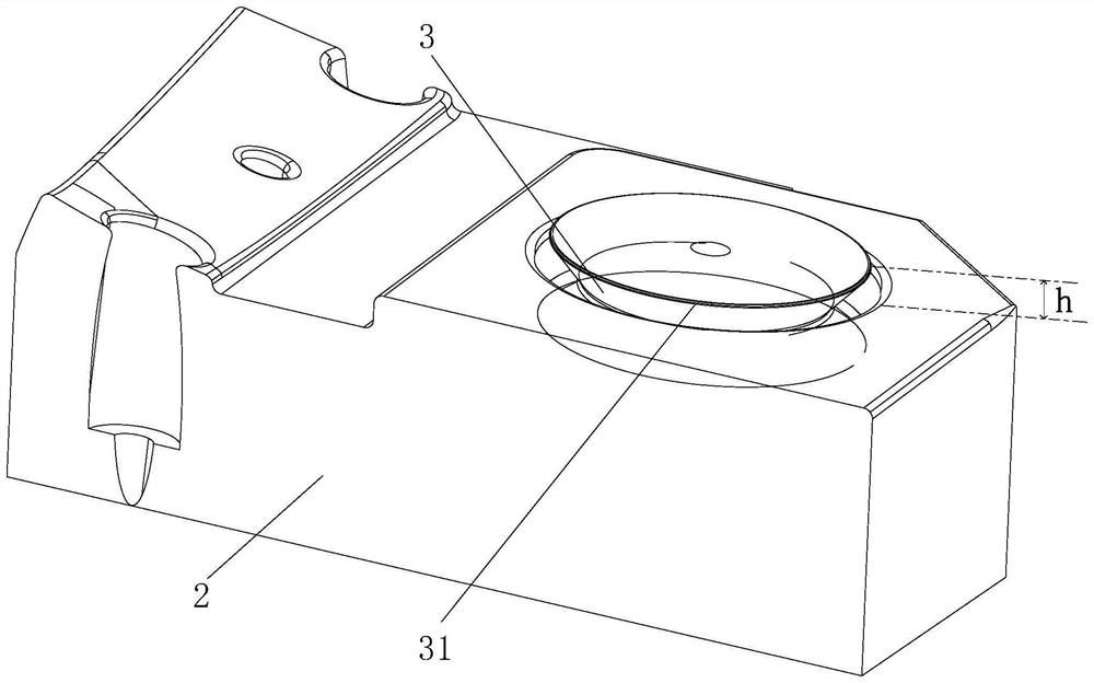
[0041] After the suction cup 3 is set on the fixed fixture 2, in its natural state, the distance between the lowest point of the disk mouth 31 of the suction cup 3 and the surface of the fixed fixture 2 is h=5.5-7mm, such as figure 2 If the distance is too short, the product 1 will be hindered by the surface of the fixture 2, and the shrinkage of the suction cup 3 will not be enough to achieve the target suction force, which may cause the suction cup 3 to be unable to be firmly adsorbed on the product 1; if the distance is too long, the suction cup 3 will The stability is poor, and the suction cup 3 is usually made of a deformable elastic material, which may cause the product 1 to shake with the suction cup 3 .
[0042] According to the size of each area on the product 1, determine the distance between the suction cup 3 and the cutting edge of the product 1 when the suction cup 3 is adsorbed on the product 1. When a certain area of ​​the product 1 is large, it can be a little farther away, and the cutting stress can be eliminated by using the properties of the product 1 itself. When the product 1 has a square area with a side length ≥ 300mm, the distance between the suction cup 3 on the product 1 and the edge to be cut of the product 1 is 20-40mm; when the side length of the product 1 ≤ 300mm, the suction cup 3 is in the The distance between the suction position on the product 1 and the to-be-cut edge of the product 1 is 15-25mm. For the overlapping parts, choose whether to refine or not according to the requirements of the cutting accuracy of product 1. If the requirements of cutting accuracy are not high, the overlapping parts can be selected arbitrarily, which is more flexible. When the requirements for the cutting accuracy of product 1 are relatively high, the specific It should be: when the product 1 has a square area with side length ≥ 300mm, the distance between the suction cup 3 on the product 1 and the to-be-cut edge of the product 1 is 22-40mm; when the side length of the product 1 is less than 300mm, the distance between The distance between the suction cup 3 on the product 1 and the to-be-cut edge of the product 1 is 15-22 mm.
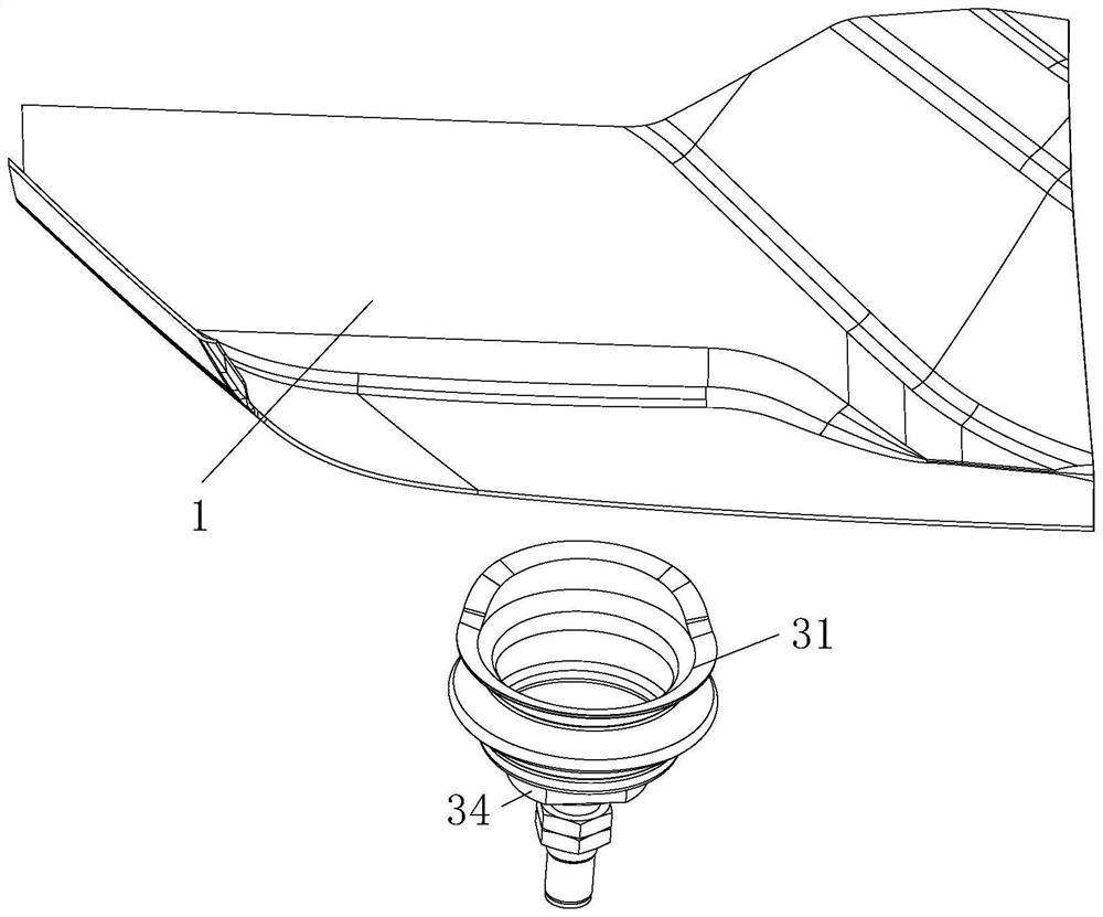
[0043] According to the degree of surface deformation and flatness of the product 1, the shape and size of the suction cups 3 are selected and the distance between the suction cups 3 is determined. The shape of the product 1 includes flatness, radius of curvature, and is used to select the shape of the suction cup 3 . At the position where the flatness of the product 1 is less than or equal to 1, it is determined that the position is relatively flat, and the adsorption of the complete suction cup 33 can ensure the adsorption fastness, such as figure 1 In the position where the radius of curvature of the product 1 is less than or equal to 100 mm, it is determined that the bending degree of this position is relatively large, and there is a gap in the disk mouth 31 of the complete suction cup 33, which will cause air leakage. Therefore, the copying suction cup 34 is adsorbed. The mouth 31 is cut into a shape consistent with the suction position of the product 1 by the complete suction cup 33, such as image 3 As shown, the cutting portion may extend to the corrugated section 32 of the suction cup 3 .
[0044] At the position where the flatness of the product 1 is less than or equal to 1, that is, in a relatively flat area, according to the size of the location area, select the size of the disk mouth 31 of the suction cup 3 and determine the distance between the adjacent suction cups 3, the area is the side length ≥ When the square area is 160mm, select the sucker 3 with the diameter of the mouth 31 of the sucker 3 being Φ90-Φ120mm, and the distance between the adjacent suckers 3 is 400-600mm; this area is a square area with a side length of ≥45mm and <160mm When the diameter of the mouth 31 of the suction cup 3 is Φ40-Φ60mm, and the distance between the adjacent suction cups 3 is 200-380mm; when the area is a square area with a side length of ≥15mm and <45mm, select a suction cup 3. The diameter of the mouth 31 is the suction cups 3 of Φ10-Φ20 mm, and the distance between the adjacent suction cups 3 is 100-200 mm, which can effectively use the elasticity of the product 1 itself to eliminate shear stress.
[0045] like Figure 4-7 As shown, the positioning method of the positioning member 4 mainly solves the positioning problem of the product 1 . By matching the surface of the product 1 with the profiling surface of the fixing jig 2, the positioning member 4 and the positioning groove 5, the product 1 is accurately fixed on the fixing jig 2. The stability of the product 1 is mainly solved by the suction of the suction cup 3, but the position of the product 1 is determined by the positioning member 4. Therefore, when the product 1 is a left-right symmetrical shape, in order to ensure that the position of the product 1 and the fixture 2 match, and If the cutting stations match, at least three sets of positioning members 4 and positioning grooves 5 are set for positioning, as a fool-proof design to prevent the product 1 from being placed backwards; when the product 1 is in a left-right asymmetric shape, at least two sets of positioning members 4 are set. For positioning with the positioning groove 5 , the surface of the product 1 and the profiling surface of the fixing fixture 2 can also be used to determine the direction of the product 1 .
[0046] like Figure 5 , 6 As shown in the figure, when each positioning member 4 is specifically arranged on the product 1, it is set on the product 1 through the perforation, the opening will cause deformation, and at the same time, it is not beautiful. Therefore, the position of the positioning member 4 cannot affect the structure of the product 1, nor can it affect the Regarding the mechanical properties of the product 1 itself, in order to avoid the structural area of ​​the product 1 , the positioning member 4 is arranged at at least one of the outer frame, inner frame, inner hole and the area to be cut of the product 1 . The outer frame or inner frame of product 1 is relatively stable in structure, and the perforation is not prone to abnormality. At the same time, when product 1 is actually used, the outer frame and inner frame are used to connect with other structures and can be blocked. Due to the design requirements of the product 1, the inner hole of the product 1 exists continuously and can be directly used as the setting of the positioning member 4. The to-be-cut area of ​​the product 1 no longer exists after cutting, and the positioning member 4 will not affect the use of the product 1 even if the mechanical properties of the area are changed.
[0047] like Figure 5-7 As shown, the peripheral surface of the positioning member 4 in the insertion direction is a tapered surface, and the side wall surface of the positioning groove 5 matches the peripheral surface of the positioning member 4 in the insertion direction, which simplifies the operation during insertion and can ensure that the product 1 remains stable during adsorption .
[0048] A hole is opened in the positioning member 4; a bottom groove 51 with a diameter smaller than its diameter is set at the bottom of the positioning groove 5. After the positioning member 4 of the product 1 is inserted into the positioning groove 5, a rod is inserted through the hole 41 of the positioning member. It is inserted into the bottom groove 51 of the positioning groove 5 and is located in the hole and the bottom groove 51 at the same time, as an auxiliary means to further ensure the accurate positioning. Since the positioning member 4 is disposed through the upper and lower surfaces of the product 1 , the hole 41 of the positioning member penetrates the positioning member 4 along the insertion direction of the positioning member 4 .
[0049] The above-mentioned embodiments are only intended to illustrate the technical concept and characteristics of the present invention, and the purpose is to enable those who are familiar with the art to understand the content of the present invention and implement accordingly, and cannot limit the protection scope of the present invention by this. All equivalent changes or modifications made according to the spirit of the present invention should be included within the protection scope of the present invention.

PUM

PropertyMeasurementUnit
Caliber90.0 ~ 120.0mm

Description & Claims & Application Information

We can also present the details of the Description, Claims and Application information to help users get a comprehensive understanding of the technical details of the patent, such as background art, summary of invention, brief description of drawings, description of embodiments, and other original content. On the other hand, users can also determine the specific scope of protection of the technology through the list of claims; as well as understand the changes in the life cycle of the technology with the presentation of the patent timeline. Login to view more.

Similar technology patents

Elastic grinding and polishing small grinding head tool

InactiveCN105033817AHigh degree of fitImprove processing quality
Owner:XIAMEN UNIV

Polishing machine

ActiveCN104097135AImprove processing quality
Owner:JIANGSU GRELIDE WATER PURIFICATION TECH

Semiconductor refrigeration suction cup

PendingCN109129255AReduce saggingImprove processing quality
Owner:TIANJIN UNIV OF TECH & EDUCATION TEACHER DEV CENT OF CHINA VOCATIONAL TRAINING & GUIDANCE +1

Classification and recommendation of technical efficacy words

  • Improve processing quality
  • Improve production yield

Control method and device of electric heating cooking device

ActiveCN103207581AImprove processing quality
Owner:ZHEJIANG SHAOXING SUPOR DOMESTIC ELECTRICAL APPLIANCE CO LTD

Substrate processing apparatus, substrate processing method, and nozzle

InactiveUS20130052360A1reduce film thickness variationimprove processing quality
Owner:SCREEN HLDG CO LTD

Roller painting reaction and reverse glazing combined process

ActiveCN103950310AImprove the packaging gradeImprove processing quality
Owner:SHANDONG HUCAI TAISHAN PRINTING CO LTD

Solid electrolytic capacitor and method for producing the same

ActiveUS6954351B2reduces weld failureimprove production yield
Owner:MURATA MFG CO LTD

Wave filter and manufacture method thereof

ActiveCN103701425AImprove production yield
Owner:ROFS MICROSYST TIANJIN CO LTD
Why Eureka
Try Eureka