Masonry filler wall

A technology for filling walls and masonry, applied to walls, buildings, building types, etc., can solve problems such as damage and economic loss, and achieve the effects of increased stability and structural strength, reduced weight, and simple device structure

Pending Publication Date: 2022-04-29
连云港市水利规划设计院有限公司
View PDF5 Cites 0 Cited by
  • Summary
  • Abstract
  • Description
  • Claims
  • Application Information

AI Technical Summary

Problems solved by technology

When an earthquake occurs, the masonry infill wall will be damaged before the structural components, causing serious economic losses, especially under medium and small earthquakes, the economic losses caused even exceed the structural components.

Method used


Image

  • Masonry filler wall
  • Masonry filler wall
  • Masonry filler wall

Examples


Embodiment 1

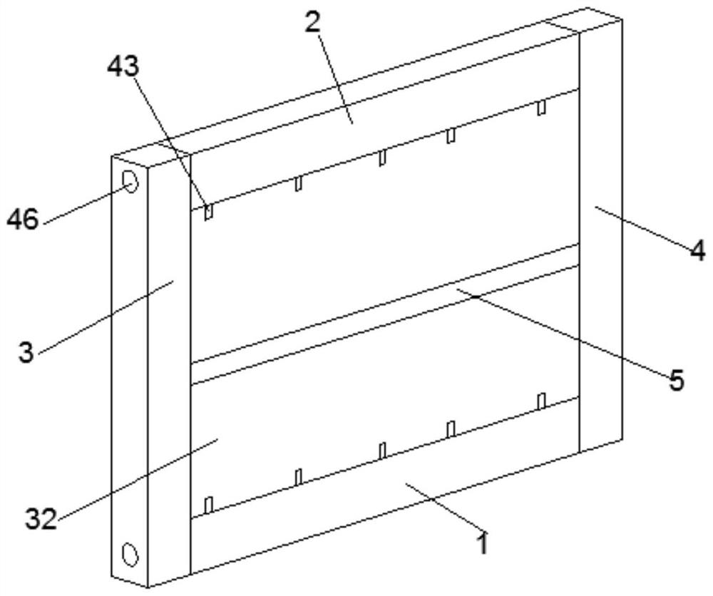
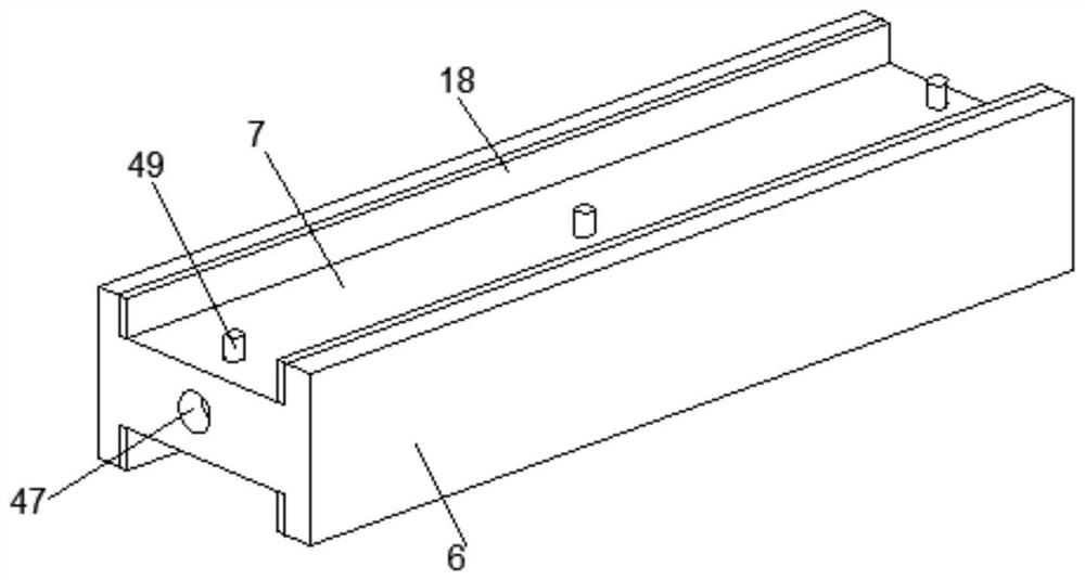
[0041] see Figure 1-8 , a masonry filled wall according to an embodiment of the present invention, comprising a lower precast concrete beam 1, an upper precast concrete beam 2, a left precast concrete column 3 and a right precast concrete column 4, the left precast concrete column 3 and the right A prefabricated connecting structure 5 is connected between the prefabricated concrete columns 4, and the prefabricated connecting structure 5 includes a prefabricated connecting horizontal plate 6, and the upper and lower sides of the prefabricated connecting horizontal plate 6 are provided with snap-in grooves 7, and the prefabricated connecting horizontal plate 6 The plate 6 is provided with a weight-reducing cavity 8, and a transverse reinforcing plate 9 is fixed in the said reducing cavity 8, and inclined supporting plates 10 are arranged symmetrically on the upper and lower sides of said transverse reinforcing plate 9, and said inclined supporting plate The other end of 10 is f...

Embodiment 2

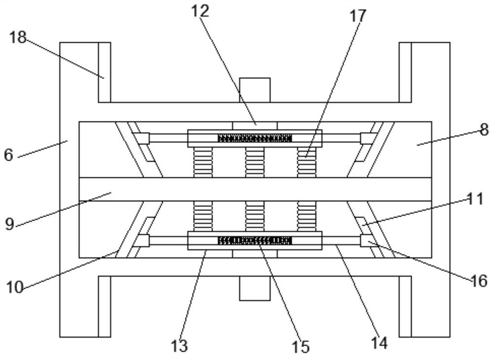
[0044] Such as Figure 7As shown, a prefabricated connection structure 5 is connected between the left prefabricated concrete column 3 and the right prefabricated concrete column 4, and the prefabricated connection structure 5 includes a prefabricated connecting horizontal plate 6, and the upper and lower sides of the prefabricated connecting horizontal plate 6 Both sides are provided with clamping grooves 7, and the prefabricated connecting horizontal plate 6 is provided with a weight-reducing cavity 8, and a transverse reinforcing plate 9 is fixed in the said reducing cavity 8, and the upper and lower sides of the transverse reinforcing plate 9 An inclined support plate 10 is arranged laterally symmetrically, and the other end of the inclined support plate 10 is fixedly connected to the inner wall of the weight-reducing cavity 8, and displacement buffer grooves 11 are provided on the inner walls of the inclined support plate 10, and the The upper and lower inner walls of the...

Embodiment 3

[0046] Such as figure 2 and Figure 8 As shown, a prefabricated connection structure 5 is connected between the left prefabricated concrete column 3 and the right prefabricated concrete column 4, and the prefabricated connection structure 5 includes a prefabricated connecting horizontal plate 6, and the upper and lower sides of the prefabricated connecting horizontal plate 6 Both sides are provided with clamping grooves 7, and the prefabricated connecting horizontal plate 6 is provided with a weight-reducing cavity 8, and a transverse reinforcing plate 9 is fixed in the said reducing cavity 8, and the upper and lower sides of the transverse reinforcing plate 9 An inclined support plate 10 is arranged laterally symmetrically, and the other end of the inclined support plate 10 is fixedly connected to the inner wall of the weight-reducing cavity 8, and displacement buffer grooves 11 are provided on the inner walls of the inclined support plate 10, and the The upper and lower in...


PUM


Abstract

The masonry infilled wall comprises a lower prefabricated concrete beam, an upper prefabricated concrete beam, a left prefabricated concrete column and a right prefabricated concrete column, a prefabricated connecting structure is connected between the left prefabricated concrete column and the right prefabricated concrete column, and the prefabricated connecting structure comprises a prefabricated connecting transverse plate; clamping grooves are formed in the upper side and the lower side of the prefabricated connecting transverse plate, a weight reduction cavity is formed in the prefabricated connecting transverse plate, a transverse reinforcing plate is fixedly arranged in the weight reduction cavity, inclined supporting plates are symmetrically arranged on the upper side and the lower side of the transverse reinforcing plate, and the other ends of the inclined supporting plates are fixedly connected with the inner wall of the weight reduction cavity; the device has the beneficial effects that the device is simple in structure and convenient to mount and fix, the whole device is convenient to assemble, the whole weight is reduced while the structural strength is not reduced, and the device has certain deformation resistance.

Description

technical field [0001] The invention relates to the technical field of design of a prefabricated frame structure masonry filling wall, in particular to a masonry filling wall. Background technique [0002] The phenomenon of earthquake disasters in recent years shows that the damage of frame structures with infill walls under earthquake action is extremely large. The study found that the collapse mechanism of frame structures with infill walls may be non-ductile. Because the masonry infill wall will participate in the seismic response, the interaction between the frame and the infill reduces the deformation space of the frame structure, which will have an adverse effect on the frame structure. Therefore, the damage phenomenon of the frame structure during an earthquake is related to the bending plasticity of the bare frame during design. The hinge failure modes are different. [0003] At the same time, the initial lateral stiffness of the masonry infill wall is low, the mat...

Claims


Application Information

Patent Timeline
Patent Type & Authority Applications(China)
IPC IPC(8): E04B2/64E04B2/66E04B1/48E04B1/98E04C2/38E04H9/02
CPCE04B2/64E04B2/66E04B1/483E04B1/98E04C2/382E04H9/025
Inventor 李明颜秉龙王朝进刘恺邵杰周路宝谢德正张言宗国营王玉甫陆洪亚朱京德
Owner 连云港市水利规划设计院有限公司
Why Eureka
Try Eureka