Hydraulic sealing system

A technology of hydraulic sealing and hydraulic rod, applied in the field of hydraulic system, can solve the problems of economic loss, large observation error, loss, etc., and achieve the effect of improving sealing effect, improving accuracy and strong fluidity

Inactive Publication Date: 2022-04-29
张泰安
View PDF0 Cites 0 Cited by
  • Summary
  • Abstract
  • Description
  • Claims
  • Application Information

AI Technical Summary

Problems solved by technology

[0004] When the existing hydraulic system is in use, the internal piston block is in contact with the inner wall of the hydraulic rod through the sealing ring, thereby sealing the contact position and ensuring the normal expansion and contraction of the hydraulic rod. However, when the hydraulic pressure is applied to the hydraulic rod, the hydraulic oil inside the hydraulic rod is also It will be squeezed. At this time, the external force of the sealing ring is large, which can easily cause the deformation of the sealing ring, so that the piston block is connected up and down, making the hydraulic pressure lose its effect. When the hydraulic pressure is in the process of lifting or lifting objects, the failure of the hydraulic pressure will make the heavy object Quick and sudden drop has a great safety hazard, and the falling of objects will also cause huge economic losses. At the same time, the hydraulic oil needs to be replaced when the hydraulic system is used. Generally, whether it needs to be replaced is manually observed. The error of human observation is huge, and it is easy to It is replaced when there is no need to replace it, thereby causing economic losses, or it is judged that it is not necessary to replace it when it needs to be replaced, which also has a greater safety hazard, so a device is urgently needed to solve the above problems

Method used


Image

  • Hydraulic sealing system
  • Hydraulic sealing system
  • Hydraulic sealing system

Examples


Embodiment Construction

[0027] The following will clearly and completely describe the technical solutions in the embodiments of the present invention with reference to the accompanying drawings in the embodiments of the present invention. Obviously, the described embodiments are only some, not all, embodiments of the present invention. Based on the embodiments of the present invention, all other embodiments obtained by persons of ordinary skill in the art without making creative efforts belong to the protection scope of the present invention.

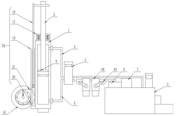
[0028] see Figure 1-6 , the present invention provides a technical solution: a hydraulic sealing system, including a first hydraulic rod 1, a second hydraulic rod 2 and an oil tank 5, the first hydraulic rod 1 is provided with a piston block 9 which is movably clamped inside, so The upper end of the piston block 9 is fixedly installed with a second hydraulic rod 2, the second hydraulic rod 2 extends to the outside of the first hydraulic rod 1, and a self-lock...


PUM


Abstract

The invention discloses a hydraulic sealing system which comprises a first hydraulic rod, a second hydraulic rod and an oil tank, a piston block is movably clamped in the first hydraulic rod, the second hydraulic rod is fixedly mounted at the upper end of the piston block, and the second hydraulic rod movably extends to the outer side of the first hydraulic rod. A piston block moves upwards along a first hydraulic rod, at the moment, a second hydraulic rod moves upwards, and when hydraulic oil is extruded, pressure enables the hydraulic oil to extrude an air bag, so that the air bag is extruded towards the interior of a sliding groove, an extrusion block is driven to move upwards, and an extrusion rod is extruded to move towards the inner side wall of a second sealing ring; the position of the inner side wall of the second sealing ring is extruded, the second sealing ring is tightly attached to the position of the inner side wall of the first hydraulic rod through extrusion, the sealing effect is improved, the second sealing ring is tensioned through extrusion, and the problem of sealing failure caused by stress deformation of the second sealing ring during use is solved.

Description

technical field [0001] The invention relates to the field of hydraulic systems, in particular to a hydraulic sealing system. Background technique [0002] Hydraulic transmission and pneumatic transmission are called fluid transmission, which is an emerging technology developed according to the principle of hydrostatic pressure transmission proposed by Pascal in the 17th century. Using water as the working medium and applying it to industry in the form of a hydraulic press gave birth to the world's first hydraulic press. In 1905, the working medium was changed from water to oil, which was further improved. [0003] Hydraulic pressure is a term in the mechanical industry and the electromechanical industry. Hydraulic pressure can be used as a power transmission method to become a hydraulic transmission. Hydraulic pressure can also be used as a control method, known as hydraulic control. Hydraulic transmission uses liquid as the working medium, and uses the pressure energy o...

Claims


Application Information

Patent Timeline
IPC IPC(8): F16J15/34F15B15/14F15B21/041F15B19/00F15B20/00
CPCF16J15/3448F15B15/1461F15B21/041F15B19/00F15B19/005F15B20/00
Inventor 张泰安
Owner 张泰安
Why Eureka
Try Eureka