
Hybrid water taking system and control method thereof

A hybrid valve control technology, applied in water supply equipment, drinking water equipment, construction, etc., can solve the problems of high engineering cost, high engineering construction difficulty, and low engineering construction difficulty, and achieve low engineering cost and high engineering construction efficiency. The effect of low difficulty and shortened construction period

Pending Publication Date: 2022-05-03
ECONOMIC & TECH RES INST OF HUBEI ELECTRIC POWER COMPANY SGCC +1
View PDF0 Cites 0 Cited by
  • Summary
  • Abstract
  • Description
  • Claims
  • Application Information

AI Technical Summary

Problems solved by technology

[0005] The purpose of the present invention is to overcome the defects and problems of high engineering cost and high engineering construction difficulty existing in the prior art, and provide a hybrid water intake system with low engineering cost and low engineering construction difficulty and its control method

Method used


Image

  • Hybrid water taking system and control method thereof
  • Hybrid water taking system and control method thereof

Examples


Embodiment 1

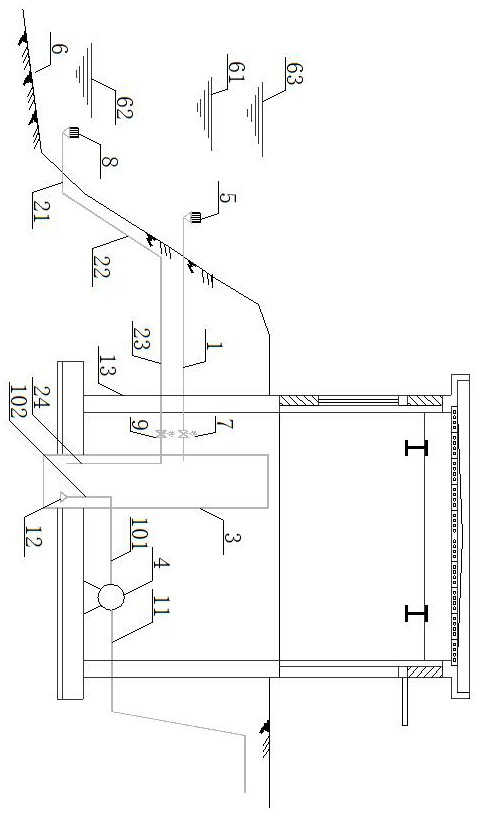
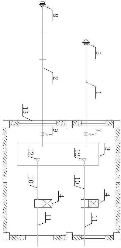
[0050] see figure 1 , figure 2 , a hybrid water intake system, the water intake system includes an artesian water diversion pipeline 1, a siphon suction water pipeline 2, a water collection tank 3 and a water pump 4; the water collection tank 3 is a closed water tank; one end of the artesian water diversion pipeline 1 It communicates with the No. 1 water intake head 5, and the No. 1 water intake head 5 is located between the normal water level 61 of the water source 6 and the low water level 62 of the water source 6. The other end of the artesian water diversion pipeline 1 communicates with the water collection tank 3, and the No. 1 control valve 7 is arranged on the artesian water diversion pipeline 1; one end of the said rainbow suction water pipeline 2 communicates with the No. 2 water intake head 8, and the No. 2 water intake head 8 is located below the low water level 62 of the water source 6. The other end of the suction water pipeline 2 communicates with the water col...

Embodiment 2

[0055] Basic content is the same as embodiment 1, the difference is:

[0056] The top elevation of the water collection tank 3 is higher than the high water level 63 of the water source 6; the lowest water level of the water collection tank 3 is the same as the elevation of the highest point of the siphon water suction pipeline 2; the top of the water collection tank 3 is provided with a maintenance manhole.

Embodiment 3

[0058] Basic content is the same as embodiment 1, the difference is:

[0059] The artesian water diversion pipeline 1 is arranged horizontally; the siphon suction water pipeline 2 includes a water inlet pipe 21, a No. 1 water delivery pipe 22, a No. 2 water delivery pipe 23, and a water outlet pipe 24 connected in sequence. The water inlet pipe 21 is arranged horizontally, and The water inlet of the water pipe 21 communicates with the No. 2 water intake head 8, and the No. 2 water delivery pipe 23 is arranged horizontally. The elevation of the No. 2 water delivery pipe 23 is higher than the low water level 62 of the water source 6, and the elevation of the No. The elevation of the artesian water diversion pipeline 1, the No. 2 water delivery pipe 23 is provided with No. 2 control valve 9, and the described water outlet pipe 24 is positioned at the inside of the water collection tank 3, and the water outlet pipe 24 is vertically arranged, and the top of the water outlet pipe 24 ...


PUM


Abstract

A mixed water taking system comprises a self-flowing water diversion pipeline, a siphon water suction pipeline, a water collection tank and a water pump. The water collecting tank is a closed water tank; one end of the self-flowing water diversion pipeline is communicated with the first water taking head which is located between the normal water level of the water source and the low water level of the water source, the other end of the self-flowing water diversion pipeline is communicated with the water collecting tank, and a first control valve is arranged on the self-flowing water diversion pipeline. One end of the siphon water pipeline is communicated with the second water taking head, the second water taking head is located below the low water level of the water source, the other end of the siphon water pipeline is communicated with the water collecting tank, and a second control valve is arranged on the siphon water pipeline; a water inlet of the water pump is communicated with one end of the water pump water suction pipeline, the other end of the water pump water suction pipeline is communicated with the water collecting tank, a water outlet of the water pump is communicated with one end of the water conveying pipeline, and the other end of the water conveying pipeline extends to a water using place. According to the design, the engineering cost is low, and the engineering construction difficulty is low.

Description

technical field [0001] The invention relates to the technical field of water supply and drainage, in particular to a hybrid water intake system and a control method thereof, which are mainly applicable to reducing project cost and construction difficulty. Background technique [0002] The design and construction of water supply system is an important subject of water supply and drainage system. Whether the choice of water supply system is reasonable or not will have a major impact on the cost of the entire project, operating costs, water supply safety, construction difficulty and management workload. The river bed type water intake structure is composed of a water intake head, a water inlet pipe, a water inlet room and a pump room. According to the different forms of water inlet pipes, the water inlet pipes include artesian pipes, siphon pipes, etc. [0003] When the artesian pipe is used to divert water, the river water enters the water collection room through the artesia...

Claims


Application Information

Patent Timeline
Patent Type & Authority Applications(China)
IPC IPC(8): E03B3/04E03B5/02
CPCE03B3/04E03B5/02E03B5/025
Inventor 章建玲许汉平
Owner ECONOMIC & TECH RES INST OF HUBEI ELECTRIC POWER COMPANY SGCC
Learn More