Composite straightening machine for chilled strip steel

A technology for straightening machine and strip steel, which is applied to forming tools, feeding devices, manufacturing tools, etc., can solve the problems of reducing the performance of steel plates, difficult to ensure the effect, damage to the surface, etc., to reduce residual stress, improve the use effect, and ensure The effect of using performance

Pending Publication Date: 2022-05-06
襄阳嘉德机械有限公司
View PDF1 Cites 0 Cited by
  • Summary
  • Abstract
  • Description
  • Claims
  • Application Information

AI Technical Summary

Problems solved by technology

[0006] In order to overcome the above-mentioned defects of the prior art, the present invention provides a composite chilled steel strip straightening machine. The technical problem to be solved by the present invention is: when the existing straightening machine straightens the steel plate, due to plastic deformation in the longitudinal direction , the speed difference between the steel plate and the straightening roller can reach 3%, thus generating additional torque, the previous overall transmission is easy to cause damage to the connecting shaft and transmission gear, and at the same time, when the speed difference between the straightening roller and the steel plate occurs, the steel plate slipping phenomenon will damage the surface , and because it is difficult to adjust the machine according to the bending degree of the steel plate itself, the yield of the strip steel is easily affected, and it is difficult to guarantee the effect of straightening, which makes the surface residual stress of the steel plate after straightening high, which reduces the performance of the steel plate and is difficult Problems that meet the needs of practical applications

Method used


Image

  • Composite straightening machine for chilled strip steel
  • Composite straightening machine for chilled strip steel
  • Composite straightening machine for chilled strip steel

Examples


Embodiment Construction

[0024] The following will clearly and completely describe the technical solutions in the embodiments of the present invention with reference to the accompanying drawings in the embodiments of the present invention. Obviously, the described embodiments are only some, not all, embodiments of the present invention. Based on the embodiments of the present invention, all other embodiments obtained by persons of ordinary skill in the art without making creative efforts belong to the protection scope of the present invention.

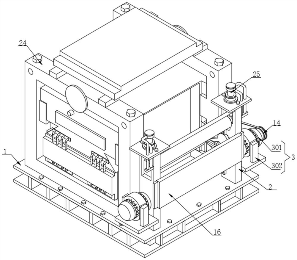
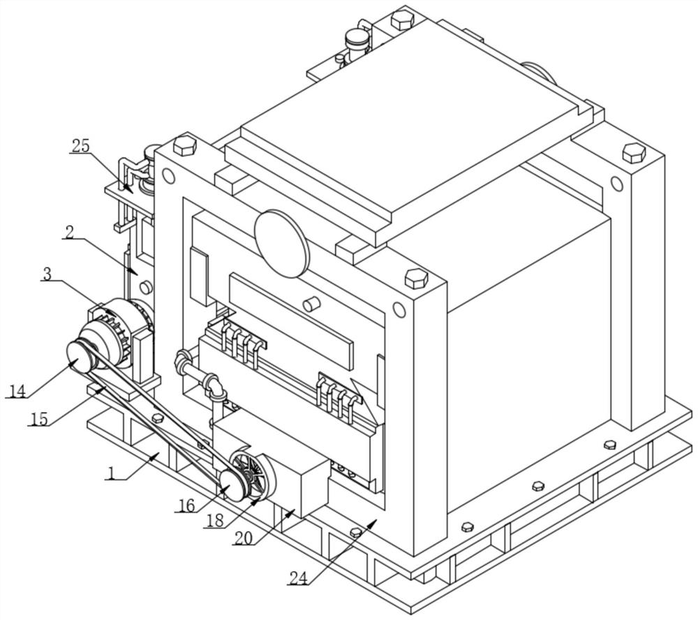
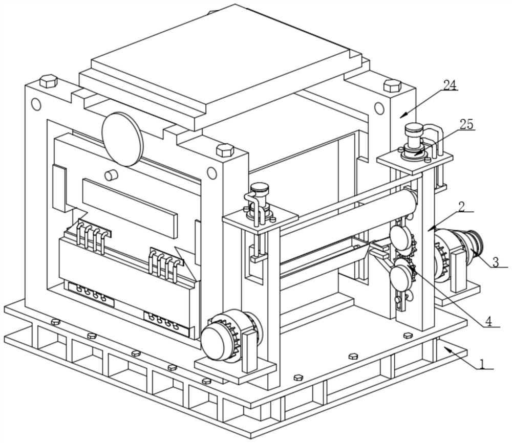
[0025] Such as Figure 1-6As shown, the present invention provides a kind of composite straightening machine for chilled and hard strip steel, comprising a processing base 1, the upper surface of the processing base 1 is fixedly connected with the lower surface of two machined vertical plates 2, and the machine located on the right side The processing vertical plate 2 is fixedly connected with a driving device 3, the driving shaft on the left side of the drivi...


PUM


Abstract

The invention discloses a chilled strip steel composite straightening machine, and particularly relates to the technical field of chilled strip steel machining, the chilled strip steel composite straightening machine comprises a machining base table, the upper surface of the machining base table is fixedly connected with the lower surfaces of two machining vertical plates, and the machining vertical plate located on the right side is fixedly connected with a driving device; a driving shaft on the left side of the driving device is fixedly connected with the right end of a rotating shaft located on the lower portion, the number of the rotating shafts is two, and the outer surfaces of the two rotating shafts are both sleeved with bearings. By arranging a transmission gear, a driving motor, an extrusion plate and a limiting sliding rod, the situation that the straightening effect of strip steel is difficult to guarantee due to the fact that the yield degree is affected is reduced, the residual stress of the straightened steel plate is reduced, the actual use performance of the steel plate is guaranteed, the strip steel can be fixed by controlling the driving motor, and similarly, the production efficiency is improved. And the strip steel can be continuously conveyed and extruded in a circulating treatment mode, so that the actual use effect of the straightening machine is improved.

Description

technical field [0001] The invention relates to the technical field of chilled strip steel processing, more specifically, the invention relates to a chilled strip steel compound straightening machine. Background technique [0002] Heat straightening is a necessary process to make the plate shape straight. Generally, it is a roller straightening machine. In actual production, in order to share a set of straightening machines for thin and thick plates and strips, the roll diameter of the straightening machine is generally small and the number of rolls is large. However, the small roll diameter will affect the straightening effect, so modern medium and heavy plate factories all use inclined four-fold 9-11 roll straightening machine. The temperature at the end of straightening is generally 650°C-750°C. If the straightening temperature is too high, the straightened steel plate may warp when it is cooled on the cooling bed; if the straightening temperature is too low, the yield...

Claims


Application Information

Patent Timeline
Patent Type & Authority Applications(China)
IPC IPC(8): B21D1/00B21D37/16B21D43/00B21D43/02
CPCB21D1/00B21D37/16B21D43/003B21D43/02
Inventor 潘高峰虞军赖会新
Owner 襄阳嘉德机械有限公司
Why Eureka
Try Eureka