
A combined machine tool and working method

A technology for combining machine tools and workpieces, which is applied in metal processing, manufacturing tools, and other manufacturing equipment/tools. It can solve the problems of high labor intensity, large production area, and low efficiency, and achieve less operators and less land occupation. Small and low energy consumption

Active Publication Date: 2022-07-19
宁波佳比佳智能科技有限公司
View PDF9 Cites 0 Cited by
  • Summary
  • Abstract
  • Description
  • Claims
  • Application Information

AI Technical Summary

Problems solved by technology

Different CNC lathes are generally used for step-by-step processing of the existing processing cross shafts, so there are problems such as high production labor intensity, high cost, low efficiency, large production area, and high energy consumption.

Method used


Image

  • A combined machine tool and working method
  • A combined machine tool and working method
  • A combined machine tool and working method

Examples


Embodiment Construction

[0063] The present application will be further described below with reference to the specific embodiments. It should be noted that, on the premise of no conflict, the embodiments or technical features described below can be arbitrarily combined to form new embodiments.

[0064] In the description of this application, it should be noted that, for orientation words, such as the terms "center", "horizontal", "longitudinal", "length", "width", "thickness", "upper", "lower" , "Front", "Back", "Left", "Right", "Vertical", "Horizontal", "Top", "Bottom", "Inside", "Outside", "Clockwise", "Counterclockwise" ” etc. indicating the orientation and positional relationship are based on the orientation or positional relationship shown in the accompanying drawings, which are only for the convenience of describing the present application and simplifying the description, rather than indicating or implying that the device or element referred to must have a specific orientation or a specific orien...


PUM


Abstract

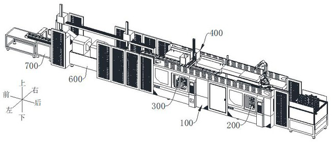
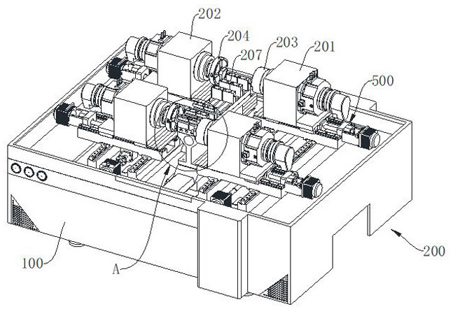
A combined machine tool of the present application includes: a frame, the frame extending in the front-rear direction; a turning part, the turning part is arranged on the rear side of the frame, and the turning part is suitable for automatic clamping Fix the workpiece and automatically process the workpiece at one time; the milling and processing part is arranged on the front side of the frame, and the milling and processing part is suitable for automatically clamping the fixed workpiece and automatically re-processing the workpiece; the loading and unloading system, the The loading and unloading system is adapted for conveying workpieces to the turning part, for unloading the workpiece from the turning part and conveying the workpiece to the milling part, and for unloading the workpiece from the milling part and The workpiece is transported out. It has the advantages of integrated station, high degree of automation and high processing efficiency.

Description

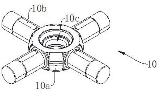
technical field [0001] The present application relates to the field of machining equipment. Background technique [0002] The automobile differential can make the left and right (or front and rear) drive wheels rotate at different speeds. The cross shaft (differential shaft) is one of the key parts of the automobile differential, which is used to transmit torque and motion; such as figure 1 As shown, the cross shaft 10 includes a base body 10a and a shaft body 10b respectively extending from the base body 10a in the front, rear, left, and right directions, and a circular hole 10c is generally provided through the base body 10a. Different CNC lathes are generally used for step-by-step processing of the existing processing cross shafts, so there are problems such as high production labor intensity, high cost, low efficiency, large production area and high energy consumption. [0003] Therefore, how to improve the existing cross shaft processing equipment to overcome the abov...

Claims


Application Information

Patent Timeline
Patent Type & Authority Patents(China)
IPC IPC(8): B23P23/02B23P15/00B23Q7/00
CPCB23P23/02B23P15/00B23Q7/00
Inventor 金佩瑾
Owner 宁波佳比佳智能科技有限公司
Learn More