Hole digging device
A round hole and hole assembly technology, which is used in earthmoving machines/shovels, construction, infrastructure engineering, etc., can solve problems such as difficulty in forming cylindrical holes, errors, errors, etc., to prevent hole deformation, ensure accuracy, and facilitate Effects of movement and control
- Summary
- Abstract
- Description
- Claims
- Application Information
AI Technical Summary
Problems solved by technology
Method used
Image

Examples
Embodiment 1
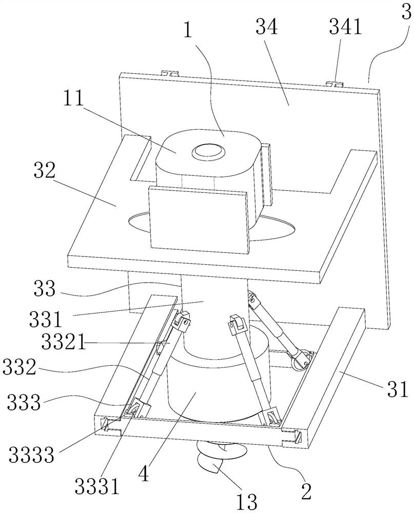
[0073] Please refer to Figure 1 to Figure 16 , the present embodiment proposes a hole-digging device for measuring the degree of road surface compaction by sand-filling method, including a hole-digging assembly 1 and a bottom plate 2, and the bottom plate 2 is provided with a standard round hole 21; specifically, the hole-digging Hole assembly 1 is used for digging holes, and the effect of described bottom plate 2 mainly has two, one is to dig holes by using the standard round hole 21 arranged on it as a reference, on the other hand, by setting the bottom plate, it is convenient to dig out The soil is placed on the base plate 2, which is convenient for collecting the excavated soil.
[0074] For specific implementation, please refer to Figure 1 to Figure 17 , the improvement of this embodiment is that it further includes a support assembly 3 and an adjustment assembly 33 . In this embodiment, the support assembly 3 is provided on the one hand to realize the adjustment asse...
Embodiment 2
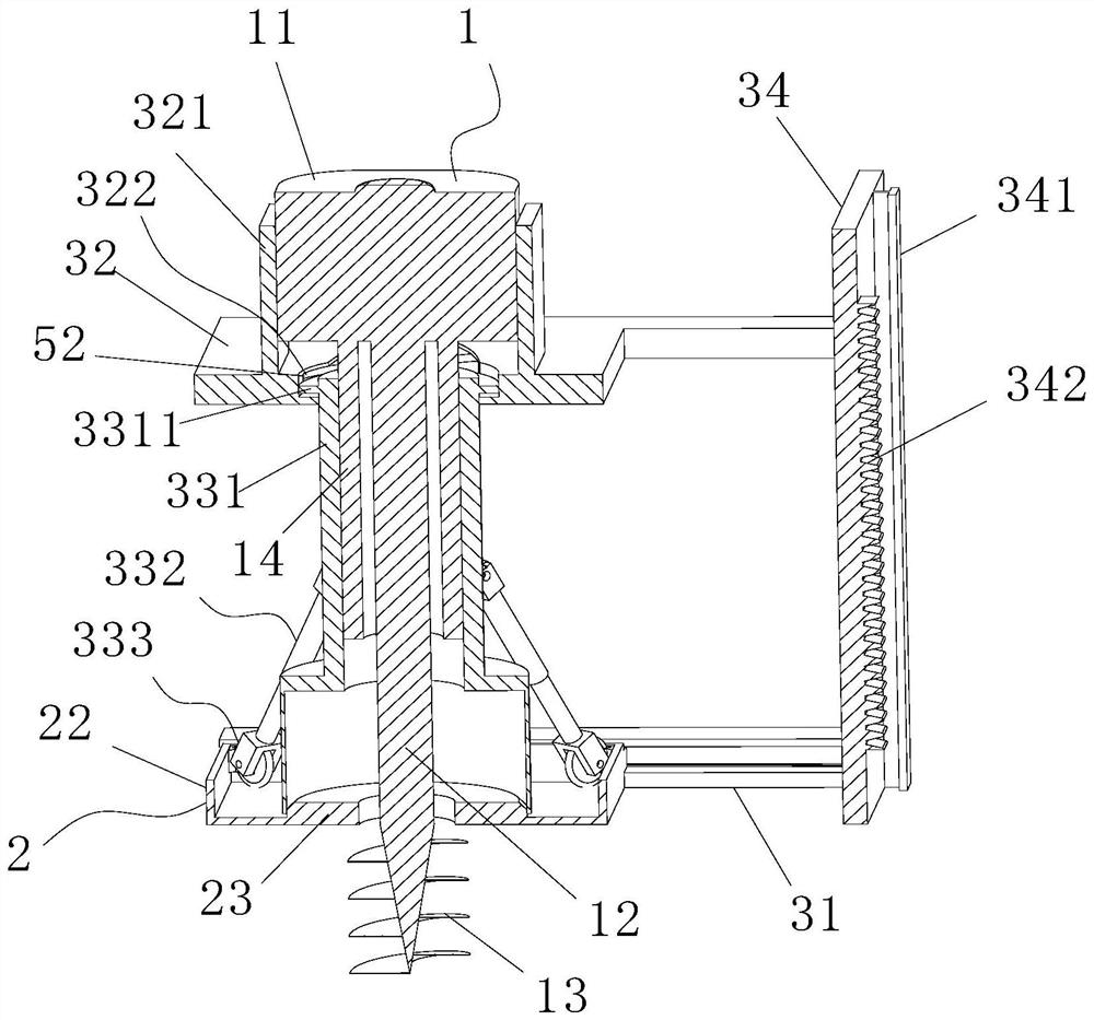
[0101] This embodiment is an improvement made on the basis of embodiment 1, and the similarities will not be repeated. The main difference is that the diameter of the head of the hole digging assembly 1 is smaller than the diameter of the standard circular hole 21 . That is, the diameter of the hole dug by the hole digging assembly 1 is smaller than the diameter of the standard round hole 21 .
[0102] In practical application, if the standard circular hole 21 and the hole-digging assembly 1 are to be completely centered through the four positioning mechanisms 333, the precision requirements for the four positioning mechanisms 333 are extremely high, that is, the four positioning mechanisms 333 must be positioned When the force and elongation are exactly the same. For this reason, by setting the diameter of the head of the hole digging assembly 1 to be smaller than the diameter of the standard round hole 21, the requirement for accuracy can be reduced. During implementation, ...
Embodiment 3
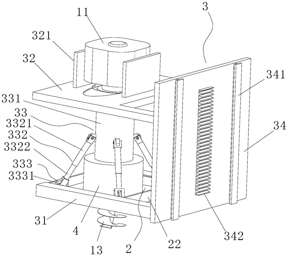
[0104] This embodiment is an improvement made on the basis of Embodiment 1. Specifically, in order to limit the rotation of the housing of the motor 11, a baffle 321 is connected to the adjustment plate 32, and the function of the baffle 321 is to limit the rotation of the motor 11. The housing of 11 rotates so that the drive shaft 12 can produce enough moment to excavate the earth.
[0105] In specific use, embodiment 1 can be positioned through the adjustment assembly 33 , and in use, the housing of the motor 11 can press the adjustment cylinder 331 to realize the downward pressure and quick adjustment of the adjustment assembly 33 . However, during this process, the motor 11 is working, which is prone to interference.
[0106] For this reason, present embodiment has been further improved:
[0107] Please refer to Figure 10 to Figure 12 and Figure 18 In this embodiment, a locking assembly 5 is added, and the locking assembly 5 is used to keep the adjustment barrel 331 i...
PUM
| Property | Measurement | Unit |
|---|---|---|
| Angle | aaaaa | aaaaa |
Abstract
Description
Claims
Application Information
 - R&D Engineer
- R&D Manager
- IP Professional
- Industry Leading Data Capabilities
- Powerful AI technology
- Patent DNA Extraction
Browse by: Latest US Patents, China's latest patents, Technical Efficacy Thesaurus, Application Domain, Technology Topic.
© 2024 PatSnap. All rights reserved.Legal|Privacy policy|Modern Slavery Act Transparency Statement|Sitemap