Boost reactor device

A voltage-boosting and piezoelectric technology, applied in transformer/inductor magnetic core, transformer/inductor cooling, transformer/inductor coil/winding/connection, etc., can solve the problem that the main body of the reactor cannot improve the cooling of the upper part of the main body of the reactor Effects, excess space, violations of compactness, etc.

Pending Publication Date: 2022-05-06
SUMIDA CORP
View PDF0 Cites 0 Cited by
  • Summary
  • Abstract
  • Description
  • Claims
  • Application Information

AI Technical Summary

Problems solved by technology

However, in the case where the end portions 503B, 504B are twisted by 90°, a welding method for joining the wide surfaces of the end portions 503B, 504B to the wide surfaces of bus bars such as terminal blocks can be employed. However, since the flat wires are twisted, extra space is required above the base core parts 510A, 510B where the coil parts 503A, 504A are not arranged, which violates the expectation of compactness and low height.
[0016] Additionally, if Figure 9C As shown in (b), with Figure 9B Similarly in (a) and (b), the height of the base core parts 510A and 510B on which the coil parts 503A and 504A are not arranged is increased so that the height of the base core parts 510A and 510B and the coil parts 503A and 504A is increased. In the case of the same shape as the height of the surface position, with Figure 9C Compared with the shape of (a), the positions of the terminal parts 503B and 504B are higher, so it further violates the expectation of compactness and low height.
[0017] Thus, when using the U-core Figure 9A , 9B , 9C, the end portions 303B, 304B, 403B, 404B, 503B, The lead-out treatment of 504B may hinder the compactness and low height of the device
[0018] Additionally, in the above Figure 9A , 9B In the boost reactor device with any structure in , 9C, it is difficult to impregnate the entire reactor body in the above-mentioned heat-conducting resin, and the cooling effect of the upper part of the reactor body cannot be improved, so the output of the boost reactor device has to be reduced. reduce

Method used


Image

  • Boost reactor device
  • Boost reactor device
  • Boost reactor device

Examples


Embodiment Construction

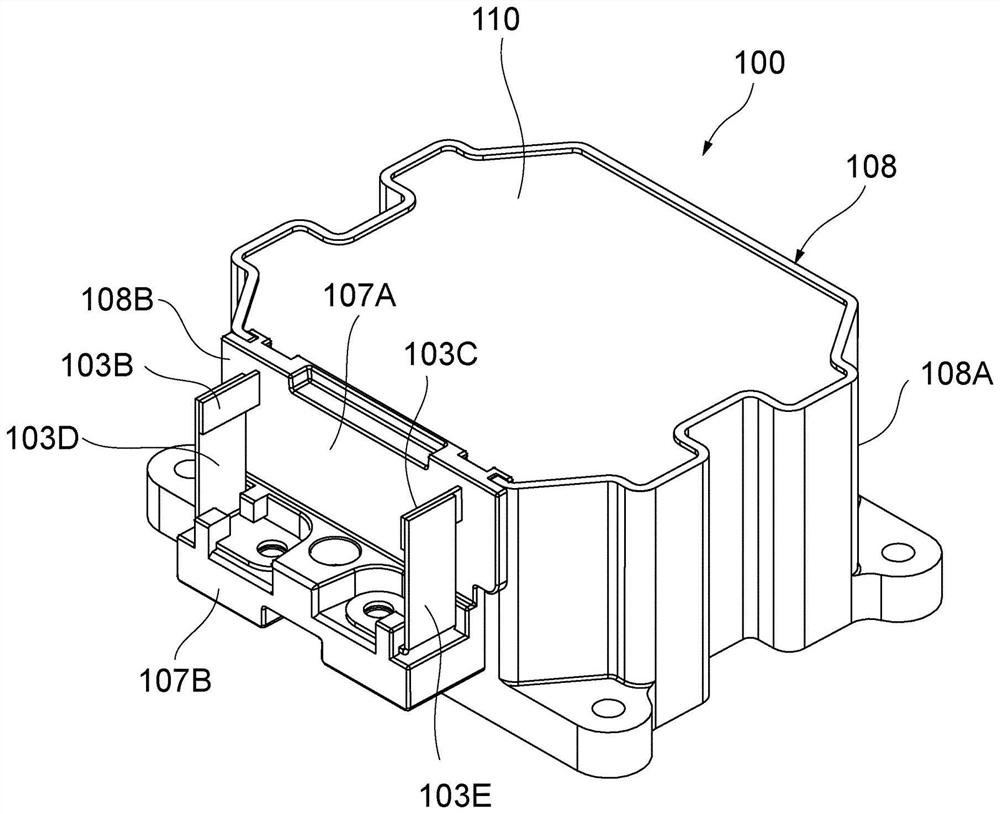
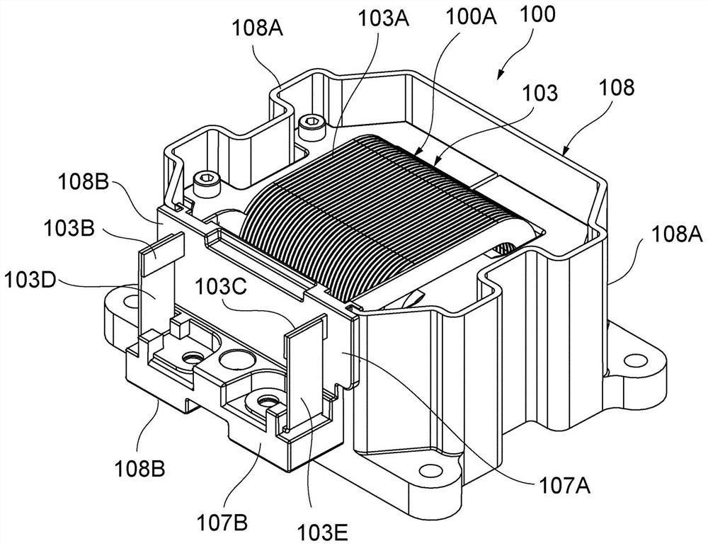
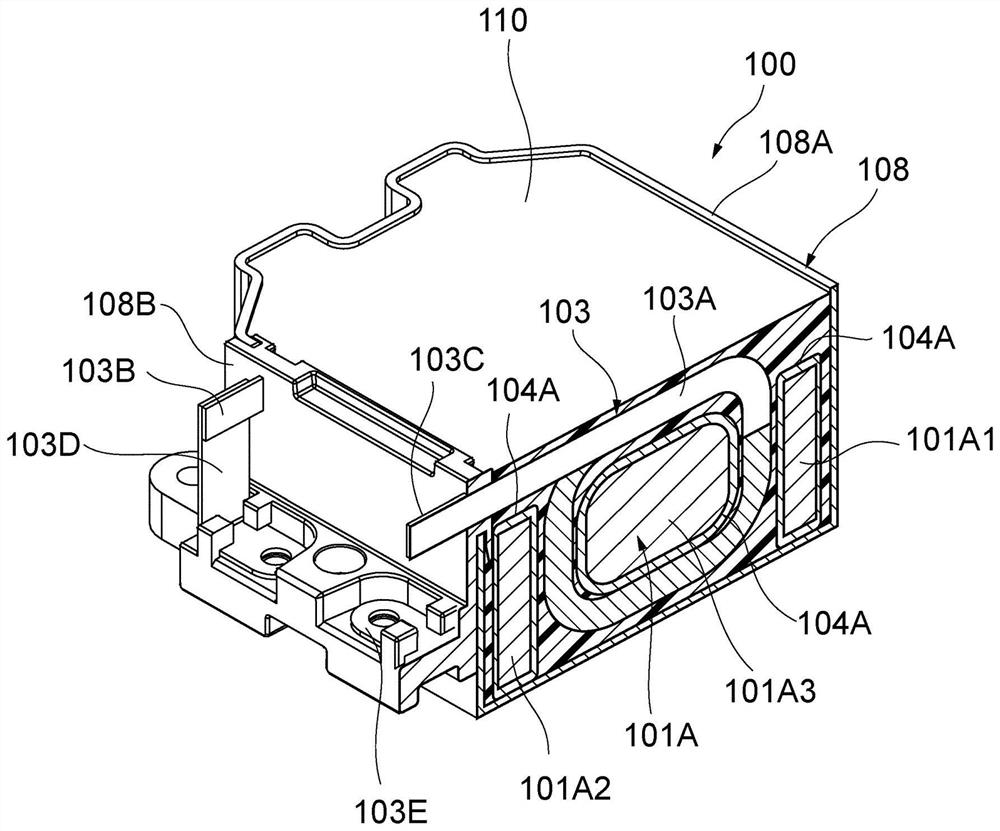
[0063] Below, use appropriately Figure 1A , Figure 1B as well as Figure 2-5 A boost reactor device according to an embodiment of the present invention will be described. The boosting reactor device 100 of the present embodiment includes: a metal case 108 whose upper part is open and made of a material having good thermal conductivity such as metal (aluminum, etc.); and a reactor assembly 100A housed in the metal case. The interior is mainly composed of E-shaped cores 101A, 101B (refer to Figure 5 (a)) and the coil part 103; and the filler 110 for cooling, which is injected between the metal case 108 and the reactor assembly 100A, and has insulating properties.

[0064]

[0065] The boost reactor device 100 according to the embodiment of the present invention includes a pair of E-shaped cores 101A and 101B (see Figure 5 (b)). The two E-shaped cores 101A, 101B pass through respective leg portions (outer leg core portions 101A1, 101B1, middle leg core portions 101A3, ...


PUM

PropertyMeasurementUnit
thicknessaaaaaaaaaa

Abstract

A step-up reactor device is provided with: an assembly (100A) in which a pair of E-shaped cores are butted in a symmetrical shape and a coil section (103A) or the like is mounted in a wound state on a middle leg core section; and a metal housing (108) formed by combining a metal housing main body (108A) having a height capable of accommodating the entire assembly, the metal housing main body being provided with a cutout portion (113) through which the input/output ends (103B, 103C) of the coil section and the like pass on a side wall portion on the side through which the input/output ends (103B, 103C) pass, and a bracket (108B) supported by engaging with an edge portion (114) of the cutout portion. A pair of through holes (111B, 111C) through which the input and output ends are tightly inserted; and a filler (110) for cooling, which is filled in the metal case so as to impregnate the entire assembly. As a result, the entire reactor main body disposed in the housing is immersed in the heat-conducting resin for cooling, and the device is compact and low in height.

Description

technical field [0001] The present invention relates to, for example, a boosting reactor device mounted on an electric vehicle or a hybrid vehicle, and specifically relates to a boosting reactor configured by winding a coil portion made of a flat wire around a part of a core constituting a closed magnetic circuit. device. Background technique [0002] For example, a boost reactor device for HEV is known in which a reactor main body is accommodated in an aluminum case and a thermally conductive resin is filled in the aluminum case for the purpose of improving heat dissipation. As the structure of the reactor main body of such a conventional boost reactor device, there is known a structure in which the front ends of both legs of a pair of U-shaped cores are butted together to form an annular core portion, and Two coil portions are arranged by winding coils made of flat wires around butted leg portions of the U-shaped core (see Patent Document 1). [0003] On the other hand, ...

Claims


Application Information

Patent Timeline
Patent Type & Authority Applications(China)
IPC IPC(8): H01F27/04H01F27/10H01F27/255H01F27/26H01F27/28H01F27/29H01F27/32
CPCH01F27/263H01F27/2847H01F27/255H01F27/29H01F27/04H01F27/324H01F27/105H01F27/2828
Inventor 山口乔之
Owner SUMIDA CORP
Why Eureka
Try Eureka